Automatic airfoil and wing design based on dynamic modeling of structural and aerodynamic performance

a technology of aerodynamic performance and automatic airfoil, which is applied in the direction of multi-objective optimisation, instruments, cad techniques, etc., can solve the problems of requiring the requirements of every aircraft subsystem, failure of one or more aircraft subsystems, and difficult and expensive generation of new aircraft designs, so as to improve the aerodynamic functionality of the aircraft, reduce the overall weight of the aircraft, and improve the effect of wing design

Active Publication Date: 2019-09-26
META PLATFORMS INC
View PDF0 Cites 22 Cited by
  • Summary
  • Abstract
  • Description
  • Claims
  • Application Information

AI Technical Summary

Benefits of technology

[0005]One or more embodiments described herein provide benefits and / or solve one or more of the foregoing and other problems in the art with systems, methods, and non-transitory computer readable media for automatically generating wing models for aircrafts by modifying quantitative design variables based on an analysis of aerodynamic and structural performance of an aircraft. In particular, the disclosed systems can utilize a lightweight optimization framework to determine cross-sectional variables for a wing of an aircraft that improve aerodynamic functionality of the aircraft and reduce overall aircraft weight while satisfying aero-structural constraints. For example, the disclosed systems can iteratively determine a wing aerodynamic performance metric and a deformation metric over a span of the aircraft wing. From this analysis, the disclosed systems can identify a variety of aero-structural performance metrics of the wing under flight conditions. Based on these aero-structural performance metrics, the disclosed systems can then modify the quantitative design variables to explore the design space and generate an improved wing design.

Problems solved by technology

Stringent operational constraints for such implementations, however, place demanding requirements on every aircraft subsystem.
These high-performance requirements often lead to flexible and thin wings resulting in aerodynamic deformities such as twisting and deflection resulting in failure of one or more subsystems of the aircraft.
Indeed, inflexibility, computational requirements, and / or simplified design models utilized by conventional design systems make new aircraft designs difficult and expensive to generate.
Although such systems provide general tools for preliminary design, they fail to provide accurate analysis of the various interactive disciplines that impact aircraft functionality.
For instance, such systems generally fail to effectively account for aerodynamic forces on an aircraft and resulting physical deformations caused as a result of the applied aerodynamic forces.
Although these tools are useful in testing performance characteristics of individual components of an existing design, they are computationally intensive and impede flexibility in aircraft design.
Indeed, individual tools for analyzing individual components of an aircraft can easily exhaust the computing resources of many conventional computing devices.
These and other problems exist with regard to conventional aircraft design systems.

Method used


Image

  • Automatic airfoil and wing design based on dynamic modeling of structural and aerodynamic performance
  • Automatic airfoil and wing design based on dynamic modeling of structural and aerodynamic performance
  • Automatic airfoil and wing design based on dynamic modeling of structural and aerodynamic performance

Examples


Embodiment Construction

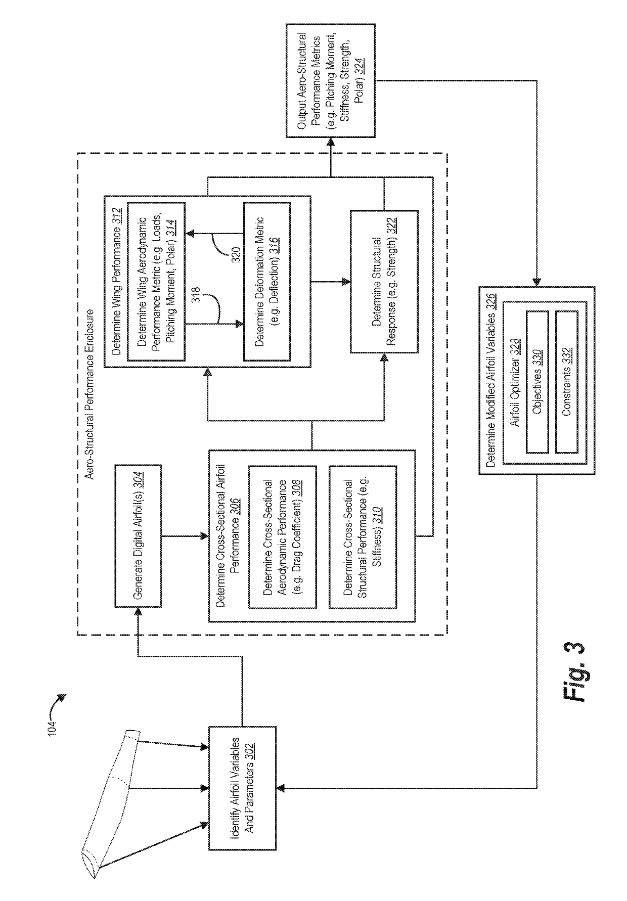
[0017]One or more embodiments of the present disclosure include an airfoil design system that generates a model aircraft wing by modifying quantitative design variables of one or more airfoils based on joint analysis of aerodynamic and structural performance. In particular, the airfoil design system can automatically generate a modified wing design by modeling detailed trade-offs between airfoil shape versus structural performance and weight. For instance, in one or more embodiments, the airfoil design system utilizes input design variables to determine cross-sectional aerodynamic and structural performance metrics for airfoils. Based on these cross-sectional performance metrics for the airfoils, the airfoil design system can iteratively determine wing aerodynamic performance and deformation metrics (across the span of the wing). In this manner, the airfoil design system can model the wing under performance loads to determine various aero-structural performance metrics. In one or mo...


PUM


Abstract

Systems, methods, and non-transitory computer-readable media are disclosed for automatically generating an improved aircraft wing by modifying quantitative design variables of one or more airfoils based on joint analysis of aerodynamic and structural performance. In particular, the disclosed systems determine cross-sectional aerodynamic and structural performance metrics for identified airfoils. Based on cross-sectional metrics, the disclosed systems iteratively determine wing aerodynamic performance and deformation metrics across a span of the wing until arriving at an equilibrium deformation and corresponding aerodynamic metric. The disclosed systems can repeatedly analyze the aero-structural metrics for different quantitative design variables to explore a design space and generate an improved wing design while improving aerodynamic and structural performance.

Description

BACKGROUND[0001]Recent years have seen significant development in aircraft design. For example, developers have recently created high-altitude, lone-endurance aircraft to provide improved digital communication capabilities. For instance, developers have generated solar-powered, high-altitude, long-endurance aircraft that provide internet connectivity in regions without other viable means of internet access. Stringent operational constraints for such implementations, however, place demanding requirements on every aircraft subsystem. For instance, the need for long endurance requires superior aerodynamic performance (e.g., high lift to drag ratios) at low Reynolds numbers enabled by efficient light-weight structures. These high-performance requirements often lead to flexible and thin wings resulting in aerodynamic deformities such as twisting and deflection resulting in failure of one or more subsystems of the aircraft.[0002]As aircraft design moves into this challenging new frontier,...

Claims


Application Information

Patent Timeline
Patent Type & Authority Applications(United States)
IPC IPC(8): G06F17/50B64C3/14
CPCG06F17/5018G06F2217/06B64C3/14G06F17/5095G06F2217/08G06F17/5086B64F5/00G06F30/15G06F30/17G06F2111/04G06F2111/06Y02T50/10G06F30/23
Inventor COLAS, DORIAN FREDERIC MARIESURYAKUMAR, VISHVAS SAMUELROBERTS, NICHOLAS
Owner META PLATFORMS INC
Why Eureka
Try Eureka