Polishing apparatus and substrate processing apparatus

Pending Publication Date: 2019-10-03
EBARA CORP
View PDF6 Cites 2 Cited by
  • Summary
  • Abstract
  • Description
  • Claims
  • Application Information

AI Technical Summary

Benefits of technology

[0032]According to the aspect of the present invention described above, since the cylindrical water drain member in which the lower end portion extends toward the liquid receiver is provided at the peripheral edge portion of the polishing table, it is possible to efficiently guide the liquid from the upper surface of the polishing table to the liquid receiver, and the cleanness around t

Problems solved by technology

In addition, in the polishing process described above, the temperature of the polishing table rises due to generation

Method used


Image

  • Polishing apparatus and substrate processing apparatus
  • Polishing apparatus and substrate processing apparatus
  • Polishing apparatus and substrate processing apparatus

Examples


first embodiment

(Polishing Apparatus)

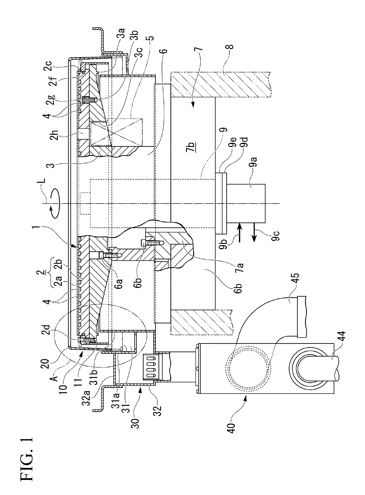
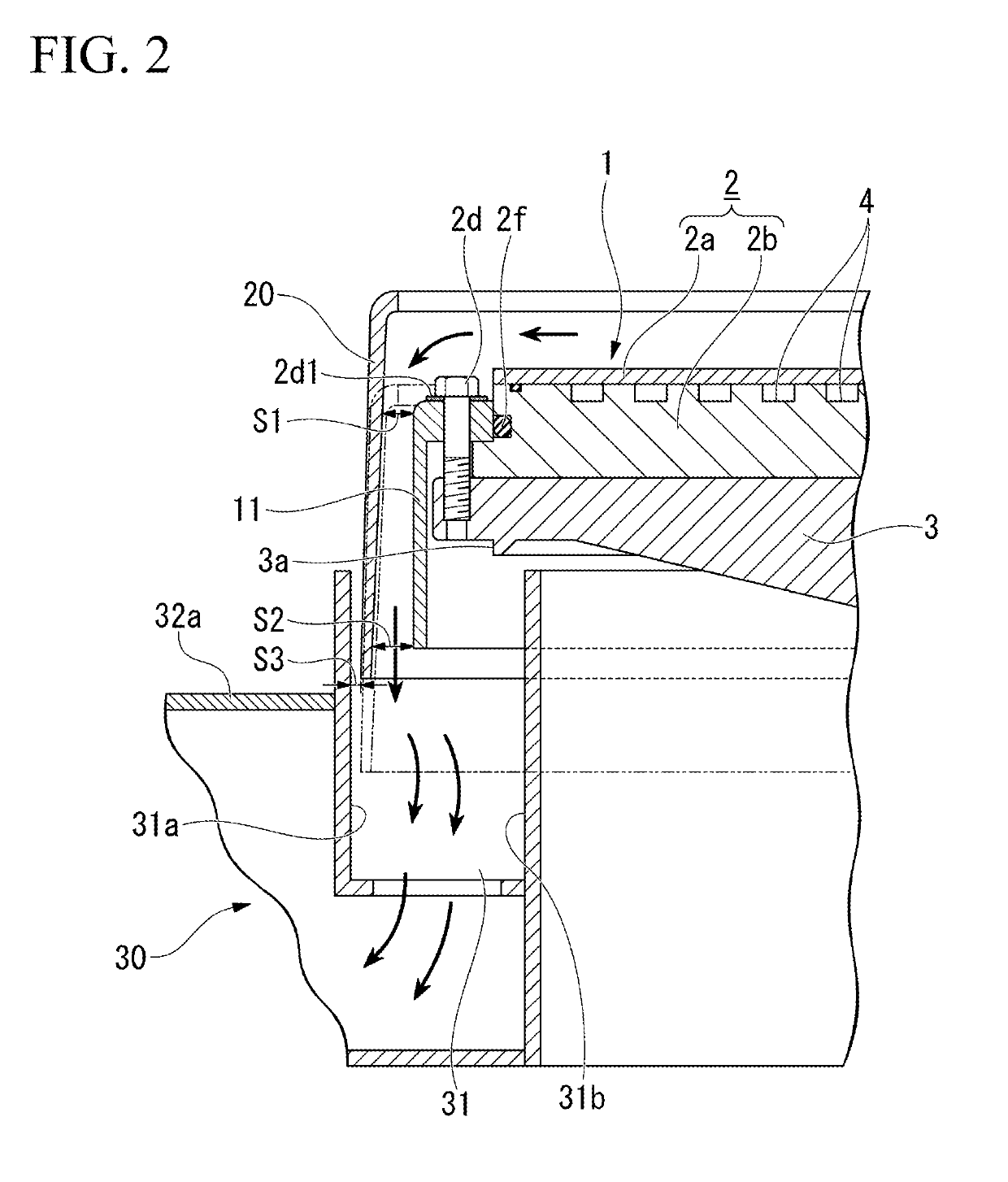
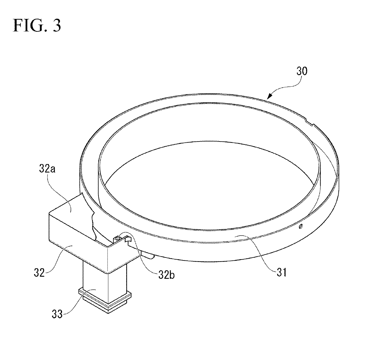
[0045]FIG. 1 is a configuration diagram of a polishing table 1 included in a polishing apparatus according to one embodiment and its peripheral structure. FIG. 2 is an enlarged view of a portion A of FIG. 1.

[0046]This polishing apparatus is incorporated in a portion of a substrate processing apparatus (described later) for processing a semiconductor substrate such as a silicon wafer. The polishing apparatus is configured to include a polishing table 1 and a top ring; however, here only the polishing table 1 is shown.

[0047]In the following description, before describing the substrate processing apparatus, the polishing table 1 of the polishing apparatus and its peripheral structure (drainage and exhaust structure 10) which is a main portion of the present invention will be described.

[0048]In the polishing table 1 shown in FIG. 1, the planar shape of the upper surface is formed in a circular shape and rotates around a central axis L passing through the center of t...

second embodiment

(Polishing Apparatus)

[0104]FIG. 6 is a configuration diagram of a polishing table 1 and its peripheral structure included in the polishing apparatus according to one embodiment. FIG. 7 is a plan view of the polishing table 1 according to one embodiment. FIG. 8 is an explanatory view showing the internal structure of the shaft 9 according to one embodiment.

[0105]In the present embodiment, different portions will be described based on the polishing apparatus of the first embodiment, and description of the same portions will be omitted.

[0106]In the heat medium flow path 4 of the present embodiment, from a side of a rotary joint 9a described later, a heat medium (such as temperature controlled water) is supplied through the shaft 9. The heat medium, as shown in FIG. 7, is supplied from a supply port 2A at a center portion of the table 2 and is discharged from the two discharge ports 2B at a center portion of the table 2. Specifically, the heat medium is supplied from the supply port 2A ...


PUM


Abstract

A polishing apparatus includes a polishing table supplied with liquid on a upper surface and rotating around a central axis, a liquid receiver having an annular shape and disposed below a peripheral portion of the polishing table, and a drain member having a tubular shape, attached to a peripheral portion of the polishing table, and including a lower end portion extending toward the liquid receiver.

Description

CROSS REFERENCE TO RELATED APPLICATION[0001]The present application claims priority based on Japanese Patent Application No. 2018-070919 filed on Apr. 2, 2018 and Japanese Patent Application No. 2018-080025 filed Apr. 18, 2018, and the contents of which are incorporated herein by reference.BACKGROUND OF THE INVENTIONField of the Invention[0002]The present invention relates to a polishing apparatus and a substrate processing apparatus.Background Art[0003]Conventionally, as one of substrate processing apparatuses for processing a substrate such as a silicon wafer, Chemical Mechanical Polishing (CMP) apparatus is known. This substrate processing apparatus includes a polishing portion (polishing apparatus) for polishing a substrate and a cleaning portion for cleaning the substrate. As disclosed in Japanese Unexamined Patent Application, First Publication No. 2017-18930, the polishing apparatus includes a polishing table and a polishing head also called a top ring. A polishing pad is att...

Claims


Application Information

Patent Timeline
IPC IPC(8): B24B57/00B24B37/24B24B37/22
CPCB24B37/22B24B57/00B24B37/24B24B57/02B24B55/03B24B37/16B24B37/015B24B37/10B24B37/013B24B53/017B24B37/34B01D19/02
Inventor SONE, TADAKAZUKOSUGE, RYUICHISHINKAI, KENJIAONO, HIROSHIAIZAWA, HIDEO
Owner EBARA CORP
Why Eureka
Try Eureka