Local reinforcement of injection moldings

Inactive Publication Date: 2019-10-03
HILTI AG
View PDF0 Cites 0 Cited by
  • Summary
  • Abstract
  • Description
  • Claims
  • Application Information

AI Technical Summary

Benefits of technology

[0005]It is an object of the present invention to solve the aforementioned problem and, in particular, to provide a method, with the aid of which the possibility of damage to a component manufactured in an injec

Problems solved by technology

Components made from plastic, e.g. polyamide, and in particular components manufactured by an injection molding process, do not have a particularly high breaking strength.
For example, one problem is that a housing component manufactured from plastic in an injection molding process, e.g. a housing for a power t

Method used


Image

  • Local reinforcement of injection moldings
  • Local reinforcement of injection moldings
  • Local reinforcement of injection moldings

Examples


Example

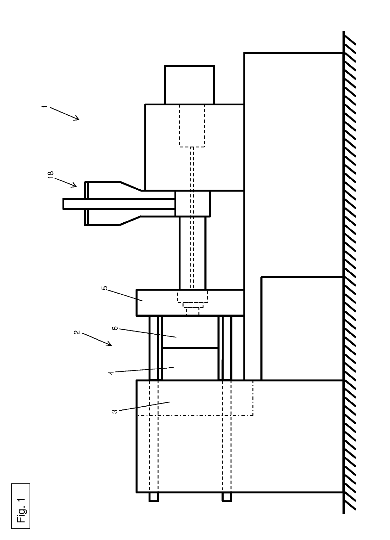
[0034]FIG. 1 shows an injection molding machine 1, including an injection mold 2. Injection mold 2 essentially contains a first mounting plate 3, including an ejector plate 4, a second mounting plate 5, including a sprue plate 6, a push-in device 7 and a carrier element 8.

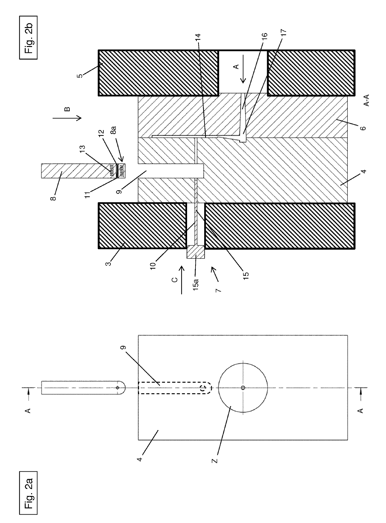
[0035]FIGS. 2a and 2b show a schematic representation of injection mold 2 for manufacturing plastic components.

[0036]Injection mold 2 may also be referred to as a mold for an injection molding machine. The plastic components may be parts, such as housing components of power tools.

[0037]As illustrated in FIG. 2b, ejector plate 4 is essentially designed as a rectangular block and includes a push-in opening 9 and a fiber channel 10. Sprue plate 6, including a centering flange Z, is illustrated in FIG. 2a.

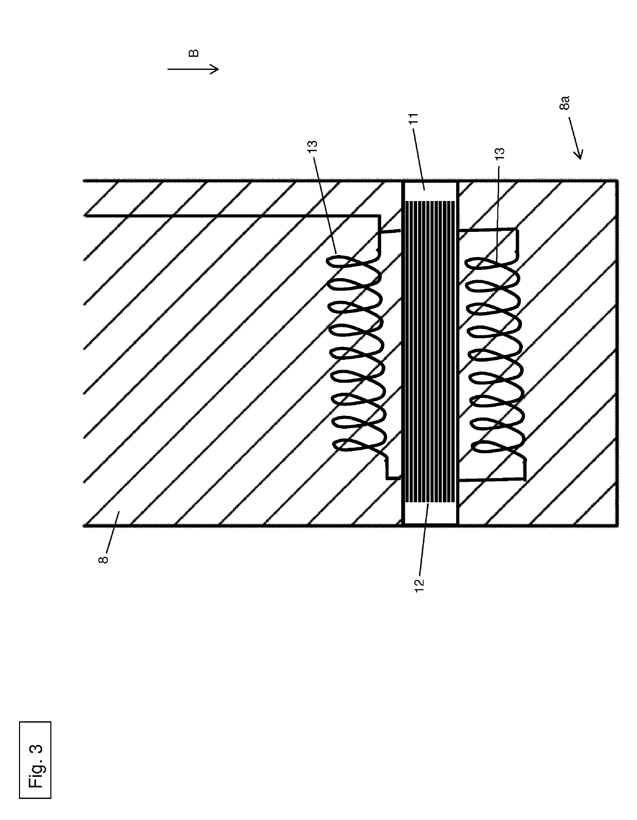
[0038]Push-in opening 9 is essentially provided with a rectangular design and extends in ejector plate 4 in direction B. Carrier element 8 may be inserted into push-in opening 9. Carrier element 8 has a certain clear...


PUM


Abstract

A method for using an injection mold for manufacturing plastic components, in particular components of power tools, the injection mold containing a sprue plate, a push-in device and an ejector plate. A cavity is between the sprue plate and the ejector plate when the sprue plate and the ejector plate are in an assembled state, and the ejector plate containing a fiber channel, through which a fiber bundle having a thermoplastic matrix is transportable to the cavity, via the push-in device, along at least part of the sprue plate. The method includes assembling the sprue plate and the ejector plate; heating the fiber bundle together with the thermoplastic matrix; positioning the fiber bundle at the cavity via the push-in device; introducing a liquid plastic into the cavity through a channel of the sprue plate; and introducing the fiber bundle into the cavity so that the fiber bundle is positioned in the cavity by the stream of liquid plastic.

Description

[0001]The present invention relates to a method for using an injection mold for manufacturing plastic components, in particular components of power tools, the injection mold containing at least one sprue plate, a push-in device and an ejector plate, and at least one cavity being provided between the sprue plate and the ejector plate when the sprue plate and the ejector plate are in an assembled state, and the ejector plate containing at least one fiber channel, through which at least one fiber bundle having a thermoplastic matrix is transportable to the cavity, with the aid of the push-in device, along at least part of the sprue plate.[0002]The present invention also relates to an injection mold for using the method.[0003]The invention furthermore relates to plastic components, in particular components of power tools, manufactured in the method.BACKGROUND[0004]Components made from plastic, e.g. polyamide, and in particular components manufactured by an injection molding process, do ...

Claims


Application Information

Patent Timeline
IPC IPC(8): B29C45/00B29C45/14B29C45/18B29C45/27
CPCB29C45/0005B29C45/2737B29L2031/28B29C45/1816B29C45/14786B29C2045/2743B29C45/14032B29C45/14631B29C45/1808B29K2105/12
Inventor LUEBKERT, ERNST-RUDOLF
Owner HILTI AG
Why Eureka
Try Eureka