Sample punching machine and sample punching mold thereof

A mold and sample punching technology, which is applied in the field of sample punching machines and sample punching molds, can solve the problems of high frequency of mold damage, waste of punching needles, and high maintenance costs of equipment, so as to reduce the frequency of mold damage, avoid waste of punching needles, and reduce equipment. The effect of maintenance costs

Inactive Publication Date: 2020-03-27
SHOUGANG JINGTANG IRON & STEEL CO LTD
View PDF7 Cites 0 Cited by
  • Summary
  • Abstract
  • Description
  • Claims
  • Application Information

AI Technical Summary

Problems solved by technology

[0004] The embodiment of the present application provides a sample punching machine and its punching die, which solves the technical problems of high die damage frequency in the prior art, which easily leads to waste of punching needles and high equipment maintenance costs, and reduces the die damage frequency and avoids The waste of punching needles greatly alleviates the damage of the abrasive tool caused by the sample being too hard, and reduces the technical effect of equipment maintenance costs

Method used


Image

  • Sample punching machine and sample punching mold thereof
  • Sample punching machine and sample punching mold thereof
  • Sample punching machine and sample punching mold thereof

Examples


Embodiment 1

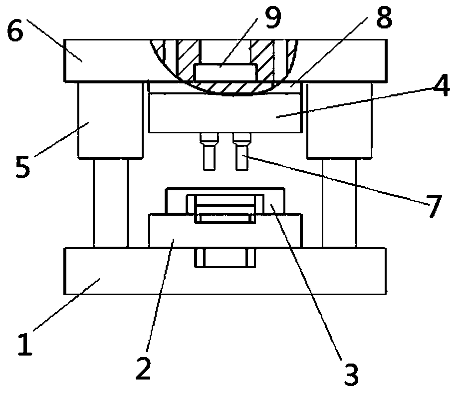
[0044] This embodiment provides a punching mold, please refer to figure 1 , The punching mold includes: a base 1.

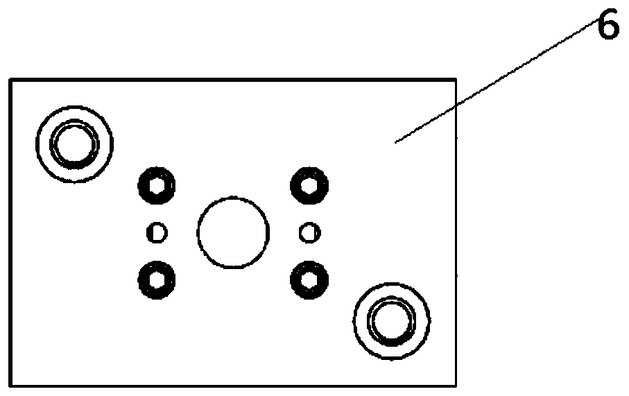
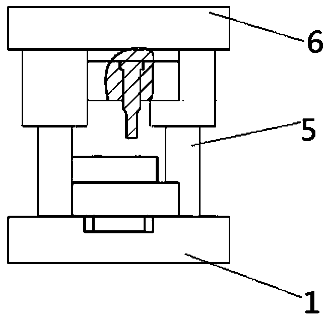
[0045] Specifically, the base 1 is a die support structure of the punching die, that is, the base 1 provides support for the die 2 and the base 1 can be used to fix the die to facilitate punching processing. Such as Figure 4 , 5 As shown in Fig. 6, in this embodiment, the shape of the base 1 is a rectangular parallelepiped structure. In actual use, the installation design can also be carried out as required, and there is no specific limitation in this embodiment. In addition, a plurality of bolt holes are opened on the base 1 for installing screws and other connecting parts. In this embodiment, it is preferable that the material of the base 1 is 45 steel and the hardness is HRC32-36. Among them, 45 steel represents high-quality carbon structural steel with a carbon content of 0.42 to 0.50%. 45 steel is a high-quality carbon structural steel with low hardness and ...

Embodiment 2

[0067] This embodiment also provides a punching machine, including the aforementioned punching die.


PUM

PropertyMeasurementUnit
hardnessaaaaaaaaaa

Abstract

The invention discloses a sample punching machine and a sample punching mold thereof, and relates to the technical field of mold design. The sample punching machine comprises a base; a female die, arranged on the base, and two punched holes being formed in the female die; a discharging plate, arranged on the female die; a male die, located over the discharging plate, and two through holes being formed in the male die; a guide column, one end of the guide column being connected with the base; an upper seat, connected with the end, away from the base, of the guide column, and the upper seat being connected with the male die; and two punching pins, the top ends of the two punching pins being correspondingly inserted into the two through holes, and the two punching pins being arranged over thetwo punched holes in a one-to-one correspondence mode, so that the technical effects that the die damage frequency is reduced, punching pin waste is avoided, the grinding tool damage situation causedby too hard samples is greatly relieved, and the equipment maintenance cost is reduced are achieved.

Description

Technical field [0001] The invention belongs to the technical field of mold design, and particularly relates to a punching machine and a punching die. Background technique [0002] The punching machine is a mechanical equipment widely used in the preparation of ferrous metal, non-ferrous metal and non-metallic plate samples. It has the characteristics of advanced structure, low noise, high efficiency, no pollution, light operation and safe operation. [0003] At present, the punching machine molds for thick and thin samples are three punching needles, punching three samples. Generally, only 2 samples are needed to analyze the oxygen and nitrogen content in molten steel to meet production requirements. However, three punching needles need to be replaced regularly during routine maintenance, which causes waste of punching needles and increases costs. Punching 3 samples requires more pressure than 2 samples, and the machine load is larger. Because the punching hole is close to the e...

Claims


Application Information

Patent Timeline
Patent Type & Authority Applications(China)
IPC IPC(8): G01N1/28G01N1/36B21D28/34B26F1/14
CPCG01N1/286G01N1/36B21D28/34B26F1/14G01N2001/366
Inventor 王明张庆振徐方虎穆晓明张冉冉李春晖高健郑明月
Owner SHOUGANG JINGTANG IRON & STEEL CO LTD
Why Eureka
Try Eureka