Method for Fast Generation of Path Traced Reflections on a Semi-Reflective Surface

Active Publication Date: 2019-10-03
SNAP INC
View PDF1 Cites 4 Cited by
  • Summary
  • Abstract
  • Description
  • Claims
  • Application Information

AI Technical Summary

Benefits of technology

The present invention introduces a new way to do real-time path tracing that is efficient, suitable for consumer computing devices, and produces photo-realistic images with reduced computational complexity. It uses a novel device called a Dynamically Aligned Structure (DAS) to carry out the intersection between secondary rays and scene geometry. This approach collectively cuts costs by using a high-speed and reducing computational complexity.

Problems solved by technology

However, the ordinary raster graphics technology is mediocre in image quality and in visual context with the real-world environment.
The desired image quality is found today in the film industry, but because of its very high computational complexity it does not fit the AR.
It suffers from long production times and requires expensive computing farms.

Method used


Image

  • Method for Fast Generation of Path Traced Reflections on a Semi-Reflective Surface
  • Method for Fast Generation of Path Traced Reflections on a Semi-Reflective Surface
  • Method for Fast Generation of Path Traced Reflections on a Semi-Reflective Surface

Examples


Embodiment Construction

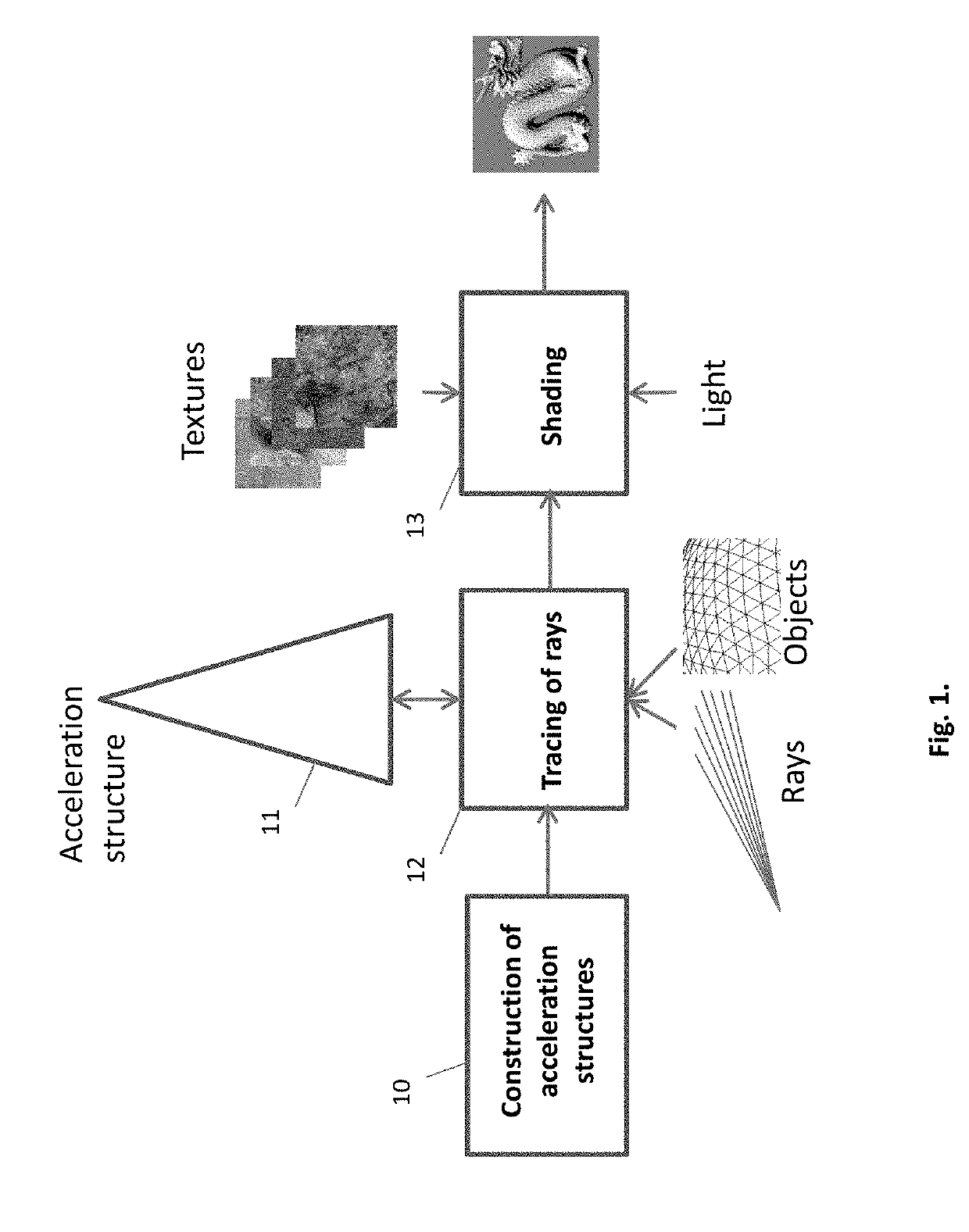
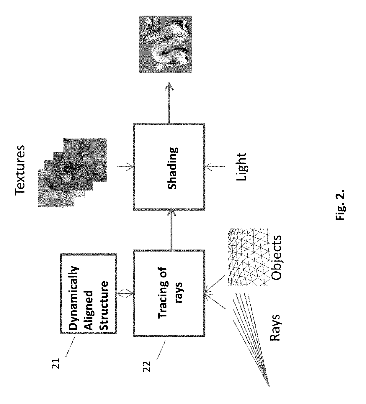
[0051]The principles and operation of an apparatus according to the present invention may be understood with reference to the figures and the accompanying description wherein similar components appearing in different figures are denoted by identical reference numerals. The drawings and descriptions are conceptual only. In actual practice, a single component can implement one or more functions; alternatively, each function can be implemented by a plurality of components and devices. It will be readily understood that the components of the present invention, as generally described and illustrated in the figures herein, could be arranged and designed in a wide variety of different configurations. Thus, the following more detailed description of the embodiments of the apparatus, system, and method of the present invention, as represented in the figures herein, is not intended to limit the scope of the invention, as claimed, but is merely representative of embodiments of the invention.

[0...


PUM


Abstract

The present disclosure describes a method of generating fast path traced physically correct reflections in a semi-reflective surface. Usage of rasterization pipeline lowers the computational complexity.

Description

CROSS-REFERENCE TO RELATED CASES[0001]The present application is a Continuation of the U.S. application Ser. No. 16 / 275,371 filed Feb. 14, 2019 entitled “System for Fast Intersections in Ray Tracing”; which is a Continuation of the U.S. application Ser. No. 15 / 640,467 filed Jul. 1, 2017 entitled “System for fast intersection of secondary rays with geometric objects in ray tracing”; which is a Continuation of the U.S. application Ser. No. 15 / 615,037 filed Jun. 6, 2017 entitled “Method for Ray Tracing Augmented Objects”; which is a Continuation-In-Part of the U.S. application Ser. No. 15 / 376,580 filed Dec. 12, 2016, which claims the benefit of U.S. Provisional Application Ser. No. 62 / 266,584, filed on Dec. 12, 2015, of U.S. Provisional Application Ser. No. 62 / 289,927, filed on Feb. 2, 2016, of U.S. Provisional Application Ser. No. 62 / 354,755, filed on Jun. 26, 2016, and of U.S. Provisional Application Ser. No. 62 / 408,730, filed on Oct. 15, 2016, all of which are hereby incorporated by...

Claims


Application Information

Patent Timeline
IPC IPC(8): G06T15/06G06T1/60G06T1/20G06T11/00G06T7/60
CPCG06T15/06G06T1/60G06T7/60G06T11/001G06T1/20
Inventor BAKALASH, REUVEN
Owner SNAP INC
Why Eureka
Try Eureka