Automatic Jet Injector for Administering Tissue

a tissue injection and automatic technology, applied in the field of medical injection instruments, can solve the problems of increasing surgery risk, and achieve the effects of preventing the finger which often presses the trigger from being hurt, moving stably, and setting the rotational speed of the power sour

Active Publication Date: 2019-10-10
BEYOUNG SCI CO LTD
View PDF34 Cites 3 Cited by
  • Summary
  • Abstract
  • Description
  • Claims
  • Application Information

AI Technical Summary

Benefits of technology

[0010]The invention has the following advantages and benefits in comparison with the conventional art: a correct, precise injection due to the electrically activated pushing board; the rod urging against the pushing board to convert a rotation of the reciprocating screw into a linear motion so that the pushing board may move stably; the control device adapted to set a rotational speed of the power source in quicker way in comparison with the conventional hand operated jet injector, thereby preventing the finger which often presses the trigger from being hurt; adjustable dosage administration; ergonomic grip; adapted to allow any of conventional syringes to mount thereon; and in case of the syringe being clogged by the tissue in the injection procedure, a warning signal indicating abnormality is generated by a circuitry of the power source, the warning signal is transmitted to a screen of the control device by the feedback module and a corresponding message “syringe replacement is required” of the warning signal is shown on the screen, thereby preventing excessive tissue from being injected into the body.

Problems solved by technology

However, the conventional hand operated jet injector 90 has the following disadvantages: complicated operations, being hand operated, not appropriate for long time operation, hurting the finger which often pushes the trigger 92, and clogged dosage in the syringe may cause excessive dosage to expel into the body of an individual, resulting in an increase of surgery risk.

Method used


Image

  • Automatic Jet Injector for Administering Tissue
  • Automatic Jet Injector for Administering Tissue
  • Automatic Jet Injector for Administering Tissue

Examples


Embodiment Construction

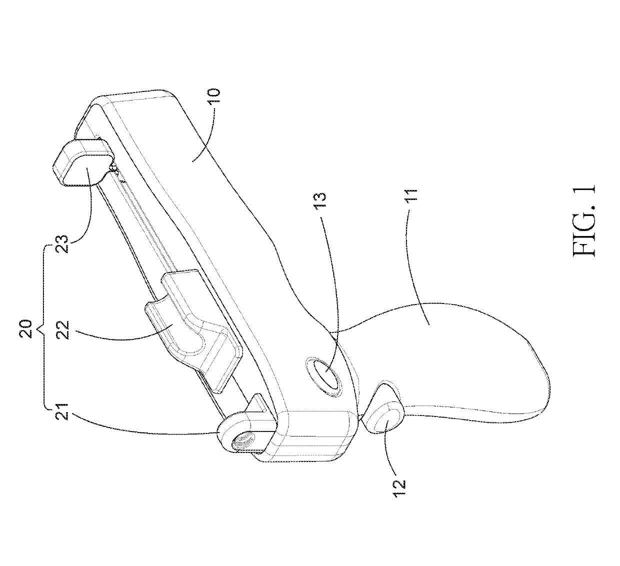
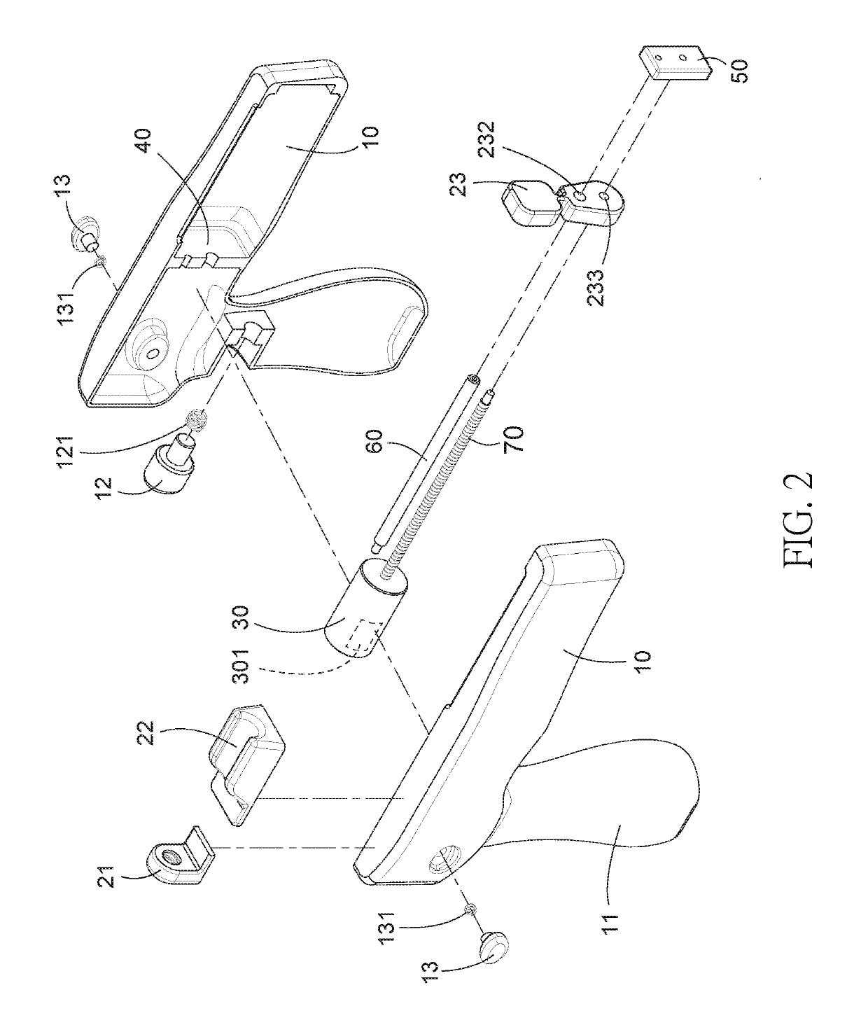
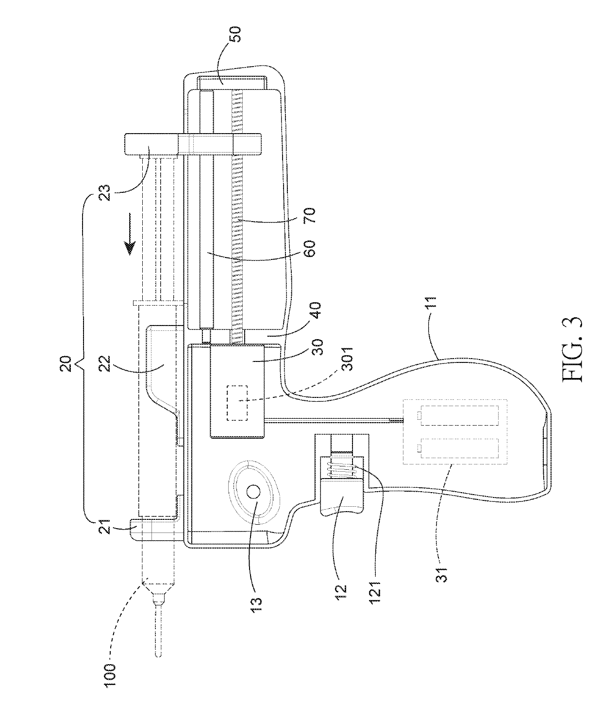
[0017]Referring to FIGS. 1 to 4, an automatic jet injector for administering tissue in accordance with the invention comprises the following components as discussed in detail below.

[0018]A housing 10 includes a downward extending grip 11 based on an ergonomic design, and a pushbutton 12.

[0019]A syringe positioning device 20 is disposed on a top of the housing 10 and includes an intermediate support 22, a front threaded fastener 21 for fastening a needle adapter of a syringe 100, and a rear pushing board 23 for pushing a plunger of the syringe 100, the pushing board 23 having at least one (one is shown) through hole 232 on a lower portion, and a threaded hole 233 under the through hole 232.

[0020]An internal fastening member 50 is disposed at a rear end of the housing 10.

[0021]A power source 30 is disposed in the housing 10 and adjacent to the grip 11. The power source 30 is electrically connected to the pushbutton 12 by wire. A power supply 31 is disposed in a compartment of the grip...


PUM


Abstract

An automatic jet injector for administering tissue is provided with a housing including a grip and a pushbutton; a syringe positioning device on a top of the housing and including an intermediate support and a rear pushing board having a lower through hole and a threaded hole under the through hole; a power source in the housing and including a power supply configured to supply power to the power source by pressing the pushbutton; a fastening member in the housing and being adjacent to a rear end of the housing; a positioning member being adjacent to the power source; a reciprocating screw having a front end operatively connected to the power source and a rear end fastened in the fastening member; a rod having a front end fastened in the positioning member and a rear end fastened in the fastening member; and a control device.

Description

BACKGROUND OF THE INVENTION1. Field of the Invention[0001]The invention relates to medical injection instruments and more particularly to an automatic jet injector for administering tissue, the jet injector adapted to allow a conventional syringe to mount thereon and being electrically activated, thereby rendering an administrating operation easy, quick and labor saving.2. Description of Related Art[0002]In aesthetic medicine procedures, a surgeon may use a jet injector to facilitate surgery. A conventional hand operated jet injector 90 is shown in FIG. 5 and comprises a syringe (not shown) filled with tissue and mounted on a top, a grip 91, a trigger 92 extending downward, forward out of the grip 91, a dosage adjustment screw 93 operatively connected to the trigger 92, a cam type positioning member 94 attached to the dosage adjustment screw 93, a helical spring 95 interconnecting the trigger 92 and the cam type positioning member 94, a pushing mechanism 96 activated by the trigger ...

Claims


Application Information

Patent Timeline
Patent Type & Authority Applications(United States)
IPC IPC(8): A61M5/30A61M5/20
CPCA61M5/30A61M5/204A61M5/2033A61M2005/2073
Inventor LEE, CHIA-CHINGCHENG, MING HSIANG
Owner BEYOUNG SCI CO LTD
Why Eureka
Try Eureka