
Radar apparatus and antenna apparatus therefor

Pending Publication Date: 2019-10-10
HL KLEMOVE CORP
View PDF5 Cites 11 Cited by
  • Summary
  • Abstract
  • Description
  • Claims
  • Application Information

AI Technical Summary

Benefits of technology

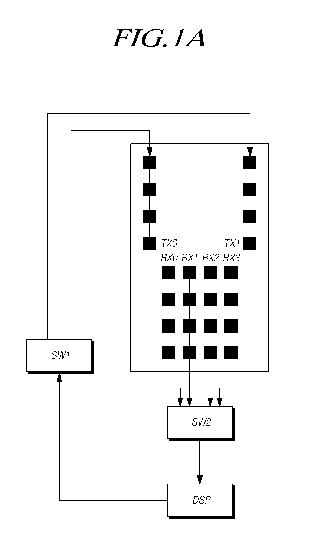
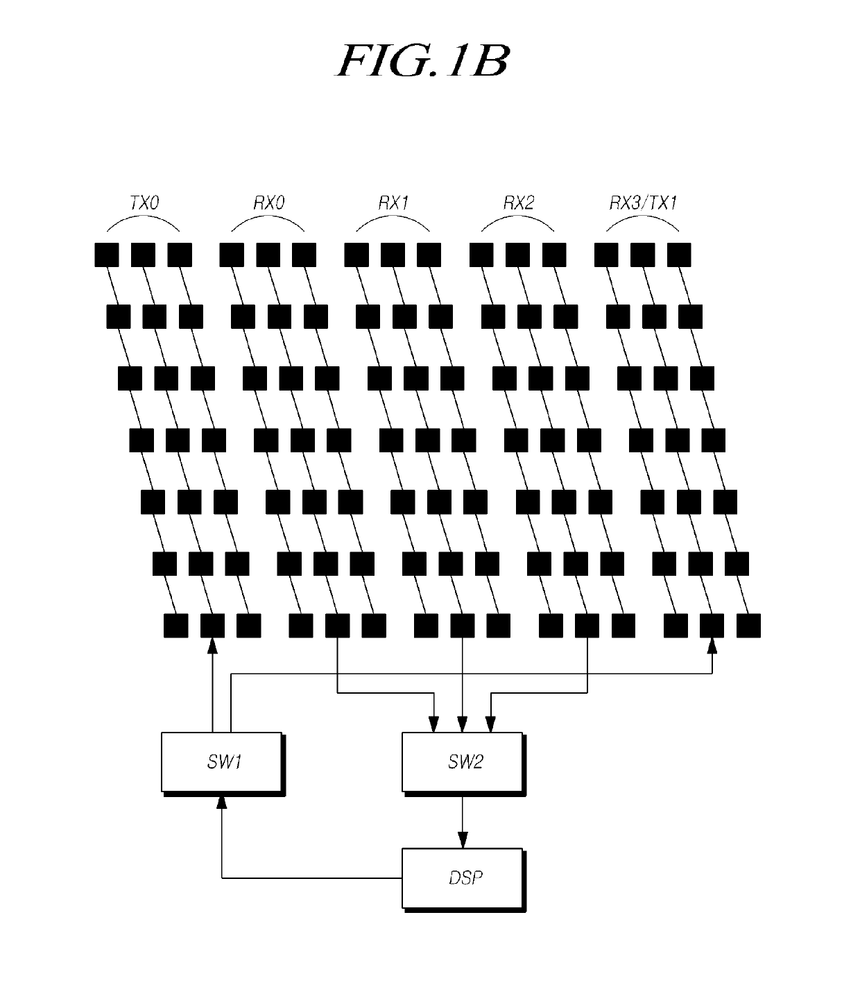
The present invention provides a radar apparatus that can maximize both mid / long-range and short-range performance through the efficient arrangement of multiple transmission and receiving antennas. The radar device can improve the measurement resolution of horizontal / vertical information of the object in both long-range and near-range detection modes while avoiding interference with other radar devices. The antenna apparatus includes two antenna elements arranged on both sides among the three transmission antennas and four receiving antennas, which can easily obtain vertical and horizontal information in both long-range and short-range detection modes. The shapes of the frequency band and the signal waveform of the transmission signal are different in the long range and short range detection modes, which improves the measurement resolution and prevents interference.

Problems solved by technology

However, at present, the portion of vehicles where a radar apparatus can be mounted is limited due to a plurality of the support structures such as an ultrasonic sensor in the bumper, the license plate and the fog lamps, so radar apparatuses are unavoidably limited in size.
However, automotive radars need to detect wide areas not only at a mid / long distance, but a short distance, so they require an additional sensor for short-range sensing, and accordingly, the costs and complication are increased.
However, performances such as resolving power of the mid / long-range radar are deteriorated and performances such as detecting range of the short-range radar are deteriorated, so their performances cannot be maximized.
Accordingly, there is a need to develop a radar apparatus that can detect both of a mid / long distance and a short distance and can be down-sized with resolution and angular resolving power maintained at a high level, but conventional radar apparatuses cannot satisfy these requirements.

Method used


Image

  • Radar apparatus and antenna apparatus therefor
  • Radar apparatus and antenna apparatus therefor
  • Radar apparatus and antenna apparatus therefor

Examples


Embodiment Construction

[0037]Hereinafter, embodiments of the present disclosure will be described with reference to exemplary diagrams. In the specification, in adding reference numerals to components throughout the drawings, it should be noted that like reference numerals designate like components even though components are shown in different drawings. Further, in describing embodiments of the present disclosure, well-known functions or constructions will not be described in detail since they may unnecessarily obscure the understanding of the present disclosure.

[0038]Further, terms such as ‘first’, ‘second’, ‘A’, ‘B’, ‘(a)’, and ‘(b)’ may be used for describing components of the present disclosure. These terms are used only for discriminating the components from other components, so the essence or order of the components indicated by those terms is not limited. It should be understood that when one element is referred to as being “connected to”, “combined with” or “coupled to” another element, it may be ...


PUM


Abstract

The present provides a radar apparatus and an antenna apparatus for the radar apparatus. Two transmission antennas disposed on both sides of the transmission antenna set may be arranged apart from each other by a predetermined vertical distance in a first direction perpendicular to the ground, and the four receiving antennas may be disposed apart from each other by a predetermined horizontal distance, so that the vertical information and the horizontal information of the object can be easily obtained in the long range detection mode and the short range detection mode.

Description

CROSS REFERENCE TO RELATED APPLICATION[0001]This application claims priority from Korean Patent Application No. 10-2018-0040831, filed on Apr. 9, 2018, which is hereby incorporated by reference for all purposes as if fully set forth herein.BACKGROUND OF THE INVENTION1. Field of the invention[0002]The present disclosure relates to a radar apparatus and an antenna apparatus, more particularly, to a radar apparatus including a multi-input multi-output (hereafter, referred to as ‘MIMO’) antenna and obtaining azimuth information and elevation information of an object at a mid / long distance and a short distance by using the antenna.2. Description of the Prior Art[0003]A radar apparatus for vehicles should have high resolution and angular resolving power. For example, automotive radars for preventing a front collision can determine interruption by extracting an angle in in-path cut-in and cut-out of a vehicle running ahead in adjacent lanes. That is, it is possible to secure safety for a d...

Claims


Application Information

Patent Timeline
IPC IPC(8): G01S13/02G01S13/93G01S13/86G01S13/42G01S7/41G01S13/931
CPCG01S13/0218G01S13/931G01S13/42G01S7/41G01S13/86G01S7/02H01Q1/3233H01Q21/00H01Q21/061H01Q21/08G01S7/028G01S2013/9327H01Q21/065G01S2013/0236H01Q21/06
Inventor LEE, JAE EUNLIM, HAE SUENGJEONG, SEONG HEE
Owner HL KLEMOVE CORP
Learn More