Ergonomic Handle for an Exercise Machine

a technology of ergonomic handle and exercise machine, which is applied in the direction of gymnastic exercise, muscle exercise devices, sport apparatus, etc., can solve the problems of not providing optimal gripping surfaces for a variety of hand sizes, not providing optimized geometry for supporting exercisers, etc., to improve hand engagement with exercise machines, reduce compressive pressure, and increase hand-to-bar surface area engagement

Inactive Publication Date: 2019-10-17
LAGREE TECH INC
View PDF8 Cites 21 Cited by
  • Summary
  • Abstract
  • Description
  • Claims
  • Application Information

AI Technical Summary

Benefits of technology

[0007]An example embodiment is directed to an ergonomic handle for an exercise machine that provides a novel improvement over traditional round handles and bars typically used as the gripping structures on exercise machines and other exercise equipment such as free weights, e.g., dumbbells and barbells. Example embodiments of the ergonomic handle for an exercise machine include an anatomically optimized, substantially polygonal-shaped gripping geometry that provides for improved hand engagement with exercise machines and equipment, and increases hand-to-bar surface area engagement when supporting substantially the weight of an exerciser, thereby reducing compressive pressure on the palm of the hand. The improved bar geometry also better accommodates a larger range of male and female hand sizes when compared to the traditional round bar geometry.

Problems solved by technology

However, they do not provide optimized geometry for supporting exercisers to engage for longer periods with exercise equipment, for instance, five minutes or more.
Moreover, they do not provide optimal gripping surfaces for a variety of hand sizes and for exercises involving both pushing and pulling forces.

Method used


Image

  • Ergonomic Handle for an Exercise Machine
  • Ergonomic Handle for an Exercise Machine
  • Ergonomic Handle for an Exercise Machine

Examples


Embodiment Construction

[0042]Various aspects of specific embodiments are disclosed in the following description and related drawings. Alternate embodiments may be devised without departing from the spirit or the scope of the present disclosure. Additionally, well-known elements of exemplary embodiments will not be described in detail or will be omitted so as not to obscure relevant details. Further, to facilitate an understanding of the description, a discussion of several terms used herein follows.

[0043]The word “exemplary” is used herein to mean “serving as an example, instance, or illustration.” Any embodiment described herein as “exemplary” is not necessarily to be construed as preferred or advantageous over other embodiments. Likewise, the term “embodiments” is not exhaustive and does not require that all embodiments include the discussed feature, advantage or mode of operation.

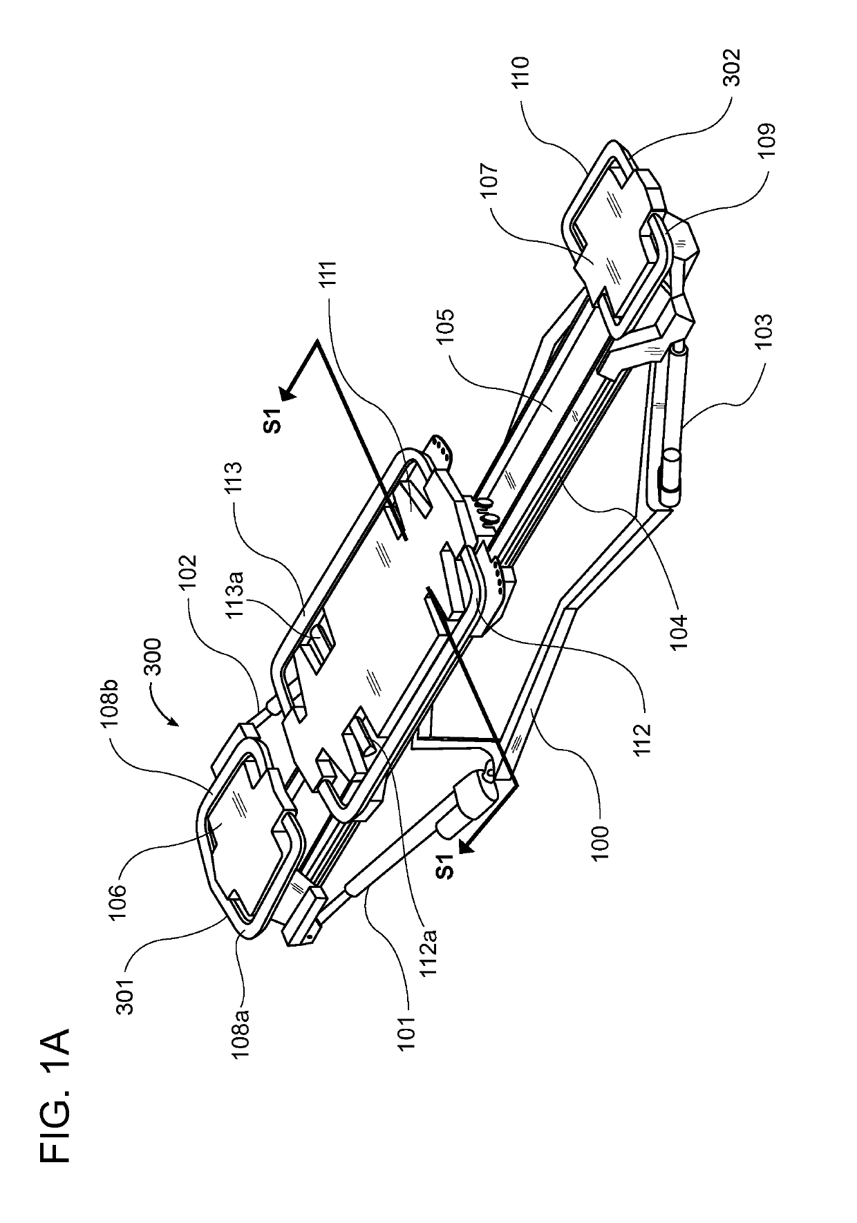
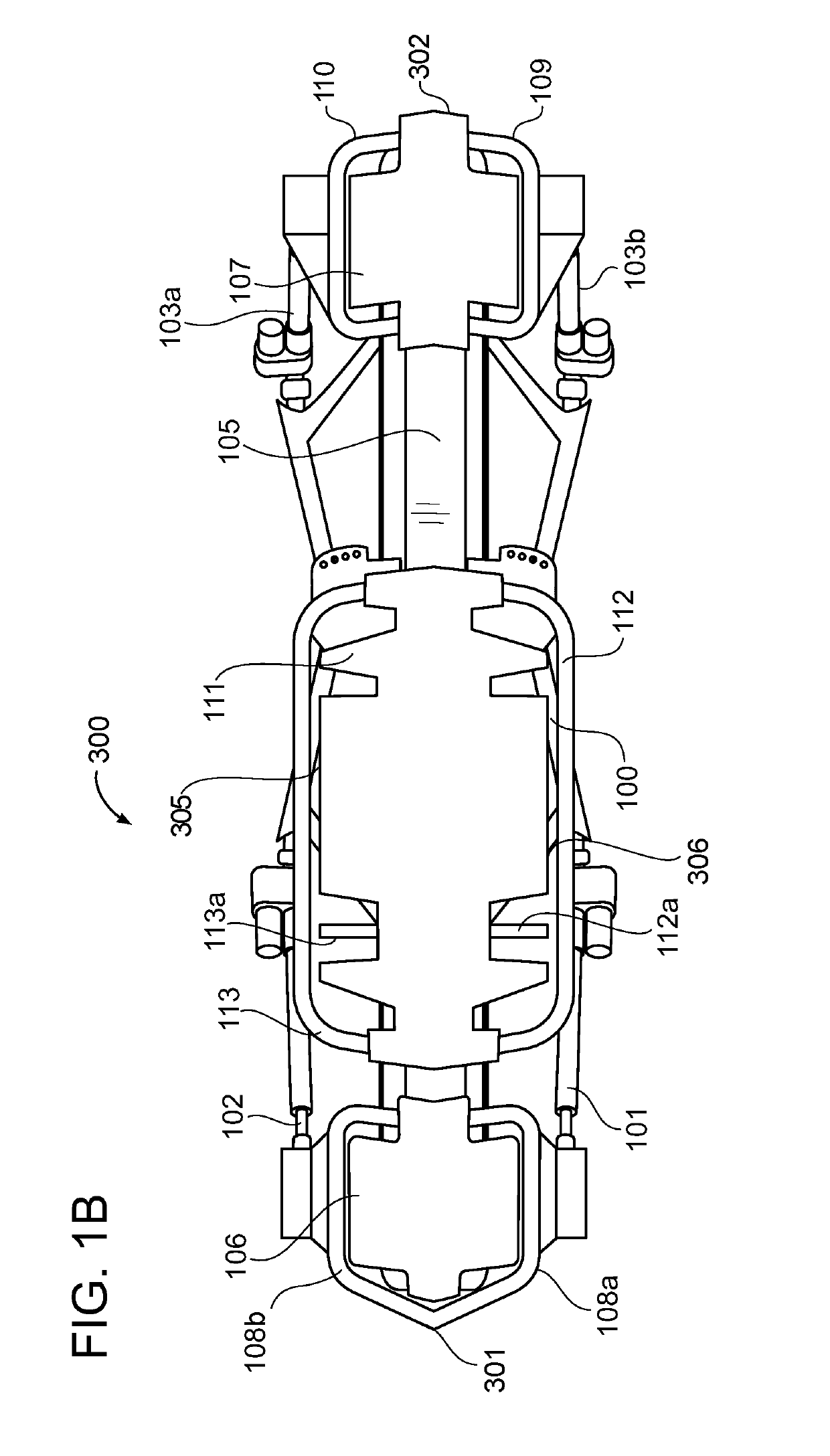
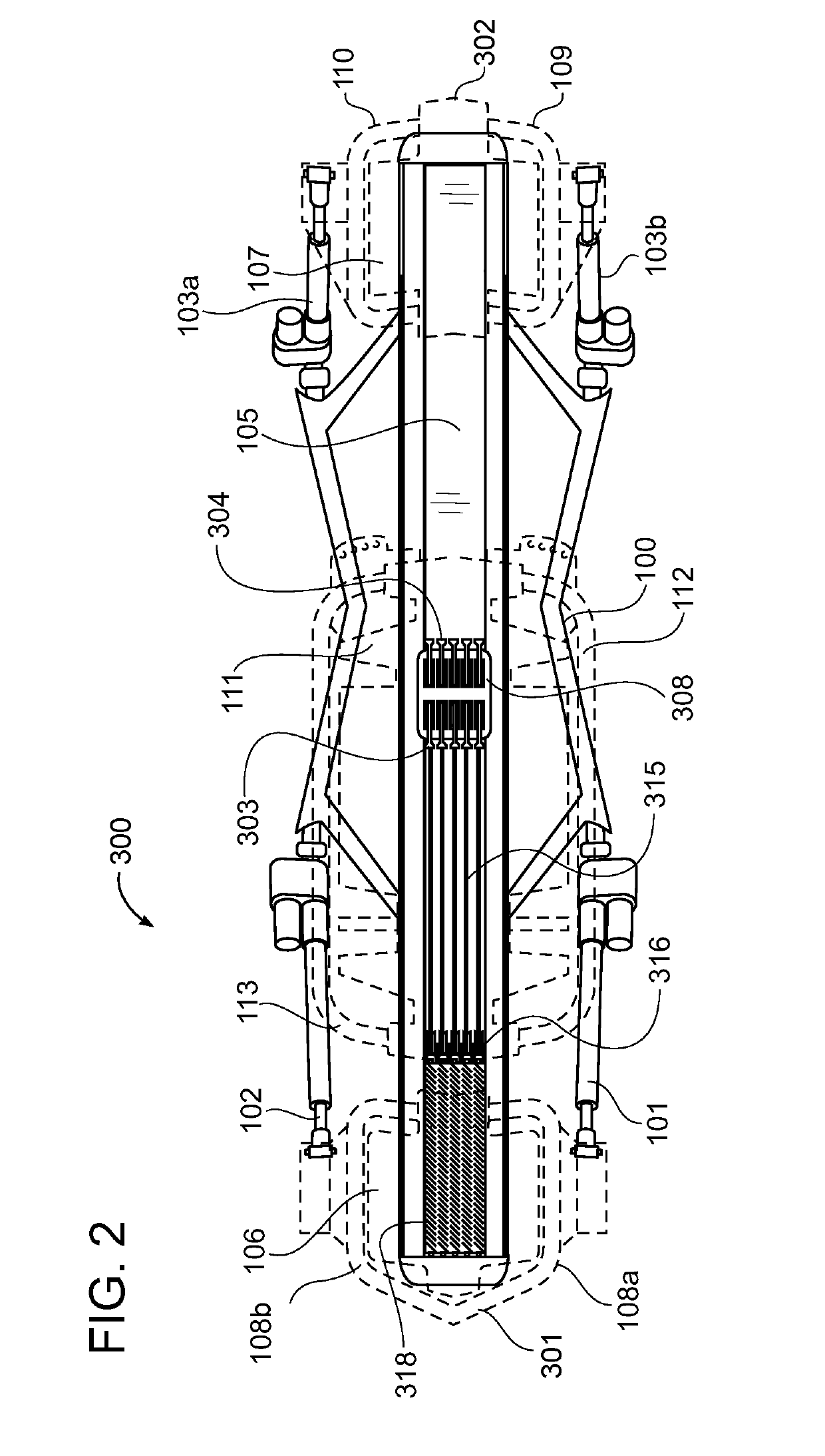
[0044]The terms “bar” and “handle” are used herein to mean a structural member of an exercise machine or exercise equipment ...


PUM


Abstract

An improved ergonomic handle for an exercise machine having a cross-sectional shape designed to more closely conform with the natural anatomical shape of a hand in a grasping position for reducing compressive pressure on the hand during exercise, improving grip, and accommodating a wide range of hand sizes. The ergonomic handle for an exercise machine generally includes solid bars and hollow tubular structures with a variety of substantially polygonal cross-sections, including various substantially triangular and trapezoidal cross-sections. Alternative embodiments include underlying bars and handles of various cross-sectional shapes with resilient cover materials having substantially polygonal cross-sections. The improved ergonomic handles may replace traditional round cross-section handles anywhere on an exercise machine they may be located.

Description

CROSS REFERENCE TO RELATED APPLICATIONS[0001]I hereby claim benefit under Title 35, United States Code, Section 119(e) of U.S. provisional patent application Ser. No. 65 / 658,240 filed Apr. 16, 2018. The 65 / 658,240 application is currently pending. The 65 / 658,240 application is hereby incorporated by reference into this application.STATEMENT REGARDING FEDERALLY SPONSORED RESEARCH OR DEVELOPMENT[0002]Not applicable to this application.BACKGROUNDField[0003]Example embodiments in general relate to the field of exercise machines and exercise equipment. More specifically, example embodiments relate to an ergonomic handle for an exercise machine having a cross-sectional shape designed to more closely conform with the natural anatomical shape of a hand in a grasping position for reducing compressive pressure on the hand during exercise, improving grip, and accommodating a wide range of hand sizes.Related Art[0004]Any discussion of the related art throughout the specification should in no wa...

Claims


Application Information

Patent Timeline
Patent Type & Authority Applications(United States)
IPC IPC(8): A63B21/00A63B21/04
CPCA63B21/4045A63B21/0442A63B21/4035A63B21/023A63B21/0428A63B21/0724A63B21/0726A63B71/0054A63B2071/0063A63B21/4031
Inventor LAGREE, SEBASTIEN ANTHONY LOUISGIBBS, ANDY H.HAMILTON, JOHN C.COX, SAMUEL D.REMUND, TODD G.WUNDERLICH, MAX
Owner LAGREE TECH INC
Why Eureka
Try Eureka