
Railway vehicle and associated traffic method

Active Publication Date: 2019-10-17
ALSTOM TRANSPORT TECH SAS
View PDF0 Cites 3 Cited by
  • Summary
  • Abstract
  • Description
  • Claims
  • Application Information

AI Technical Summary

Benefits of technology

The invention proposes a railway vehicle with an improved suspension system that can damp the movement phases of the vehicle. The suspension system includes a jack that can go from a passive to an active configuration to modify the distance between the car and the chassis. The jack is connected to a power supply device that can power the upper and lower chambers of the jack. The power supply device includes an accumulator and a pressure discharge reservoir. The jack can also be connected to a damping device that can damp the oscillations in the elevation direction between the jack and the chassis. The invention also relates to a traffic method of a rail vehicle where the jack is used to damp the oscillations in the elevation direction during travel and to adjust the distance between the car and the chassis when stopping at a platform.

Problems solved by technology

However, this system is not fully satisfactory.
The presence of the jack mechanically connecting the car and the bogie increases the stiffness of the system, thus deteriorating the vertical damping of the overall suspension system between the car and the bogie.

Method used


Image

  • Railway vehicle and associated traffic method
  • Railway vehicle and associated traffic method
  • Railway vehicle and associated traffic method

Examples


second embodiment

[0137]A second traffic method of the railway vehicle 10 comprising the power supply device 138 will now be described.

[0138]The second traffic method differs from the first traffic method in that during the fourth step, the “4 / 3” valve 94 enters the third position connecting the lower chamber 56 to the secondary accumulator 86 and the upper chamber 54 to the reservoir 78.

[0139]The valve 90 is opened so that the secondary accumulator 86 pressurizes the lower chamber 56. The lower chamber 56 increases in volume and thus drives the movement of the piston 52 toward the car 14.

[0140]The distance between the car 14 and the chassis 28 therefore decreases in a controlled manner owing to the position detector 75, the pressure in the lower chamber 56 being able to be regulated by alternatively opening and closing the valve 90.

third embodiment

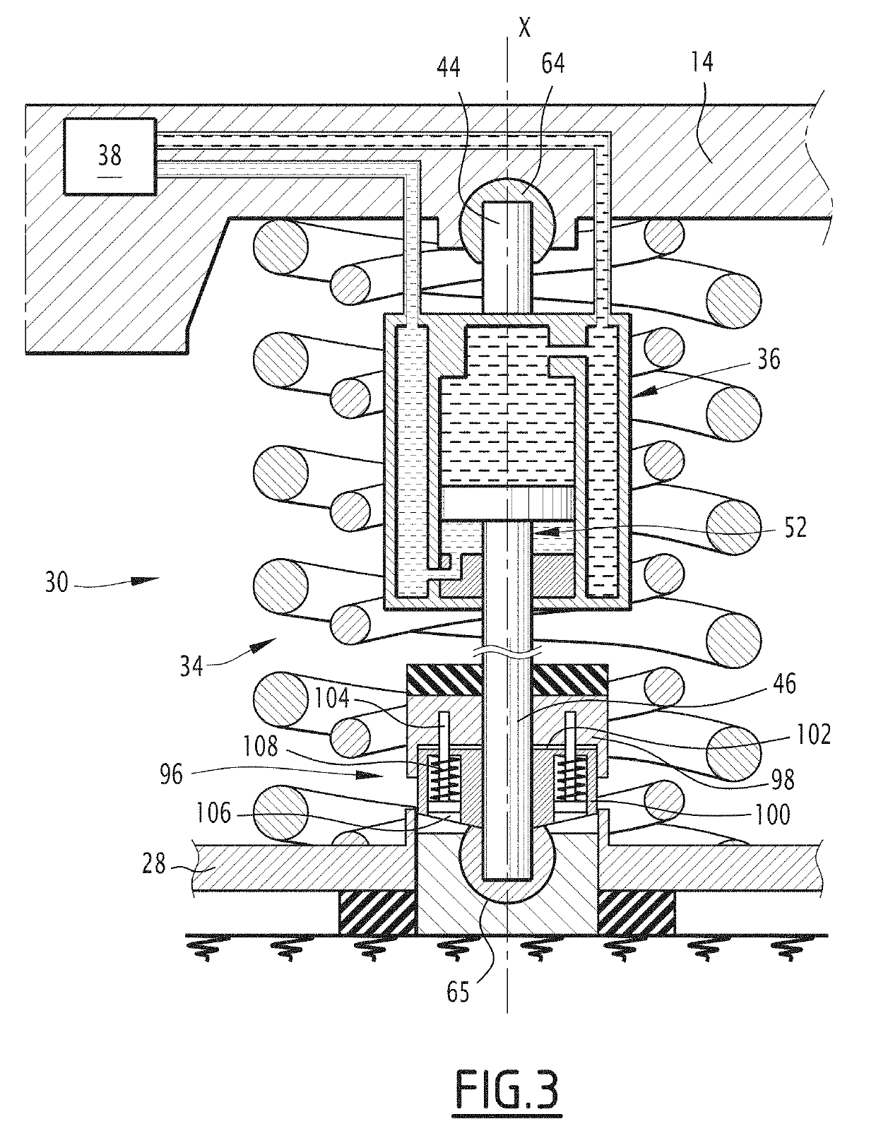
[0141]the invention is shown in FIG. 3 and will be described below.

[0142]In the third embodiment of the invention, the jack 36 further comprises a damping device 96.

[0143]The damping device 96 is located between the second end 46 of the jack 36 and the second knuckle joint 65.

[0144]The damping device 96 comprises two parts 98 and 100.

[0145]The first part 98 is connected to the second end 46 of the jack 36 and the second part 100 is connected to the second knuckle joint 65.

[0146]The first part 98 defines a cavity 102 in which the second part 100 can be inserted.

[0147]The first part 98 and the second part 100 are connected at least by a rod 104.

[0148]The first end of the rod 104 is fastened on the first part 98.

[0149]The second end of the rod 104 is free to slide in a channel 106 defined by the second part 100.

[0150]The damping device 96 comprises at least one return spring 108 placed in the channel 106 and connected to the second end of the rod 104.

[0151]The return spring 108 constra...


PUM


Abstract

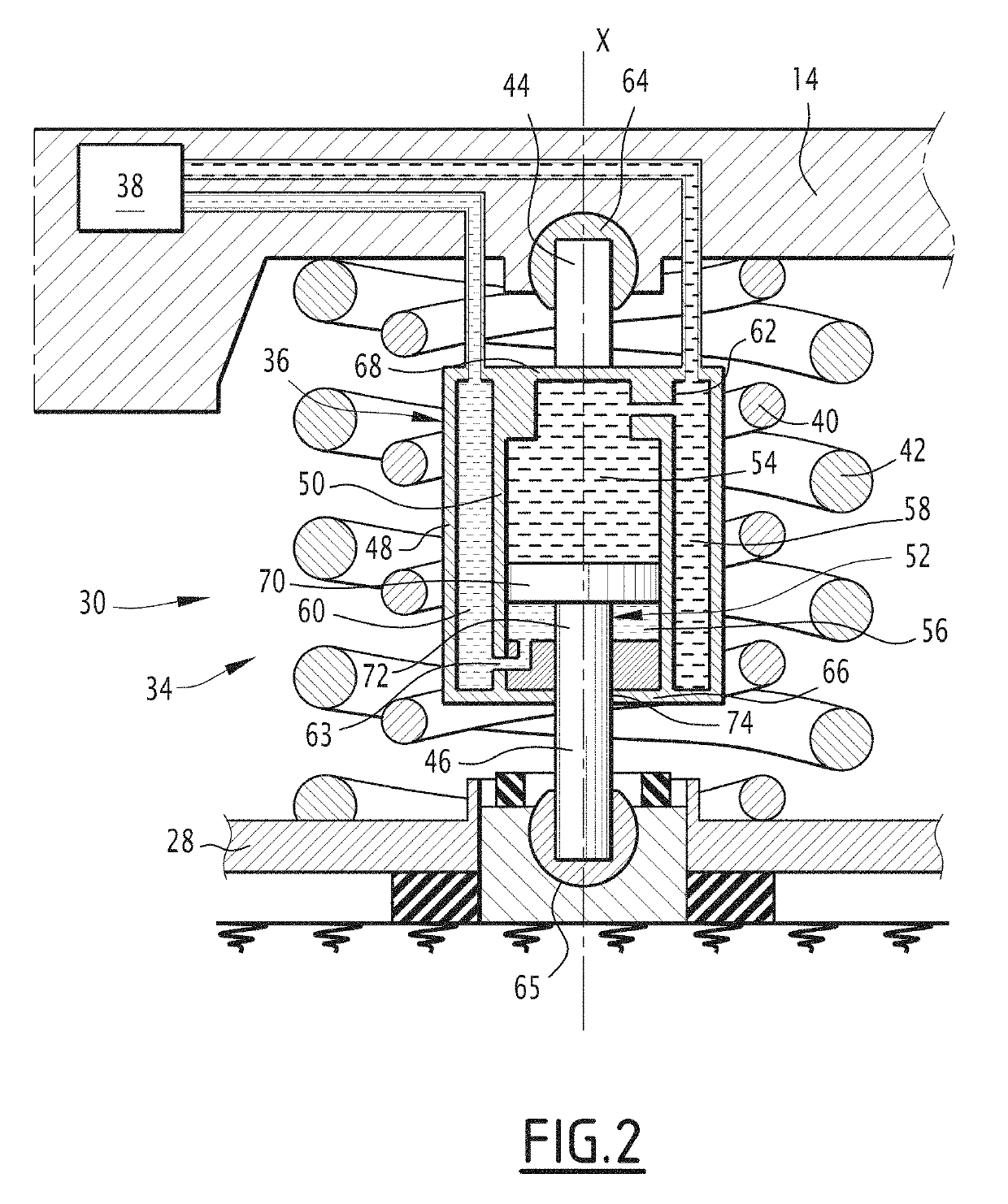
Disclosed is a railway vehicle with a car and a bogie. The bogie includes a chassis and a secondary suspension system. The secondary suspension system includes a jack and a power supply device of the jack fluidly connected to the jack by at least one flow limiter. The jack is configured to go from a first so-called passive configuration, in which the supply device is inactive, the jack then being able to passively damp the oscillations between the car and the chassis using the flow limiter, to a second so-called active configuration in which the supply device is configured to supply the jack in order to modify the distance between the car and the chassis or in order to keep the distance constant between the car and the chassis.

Description

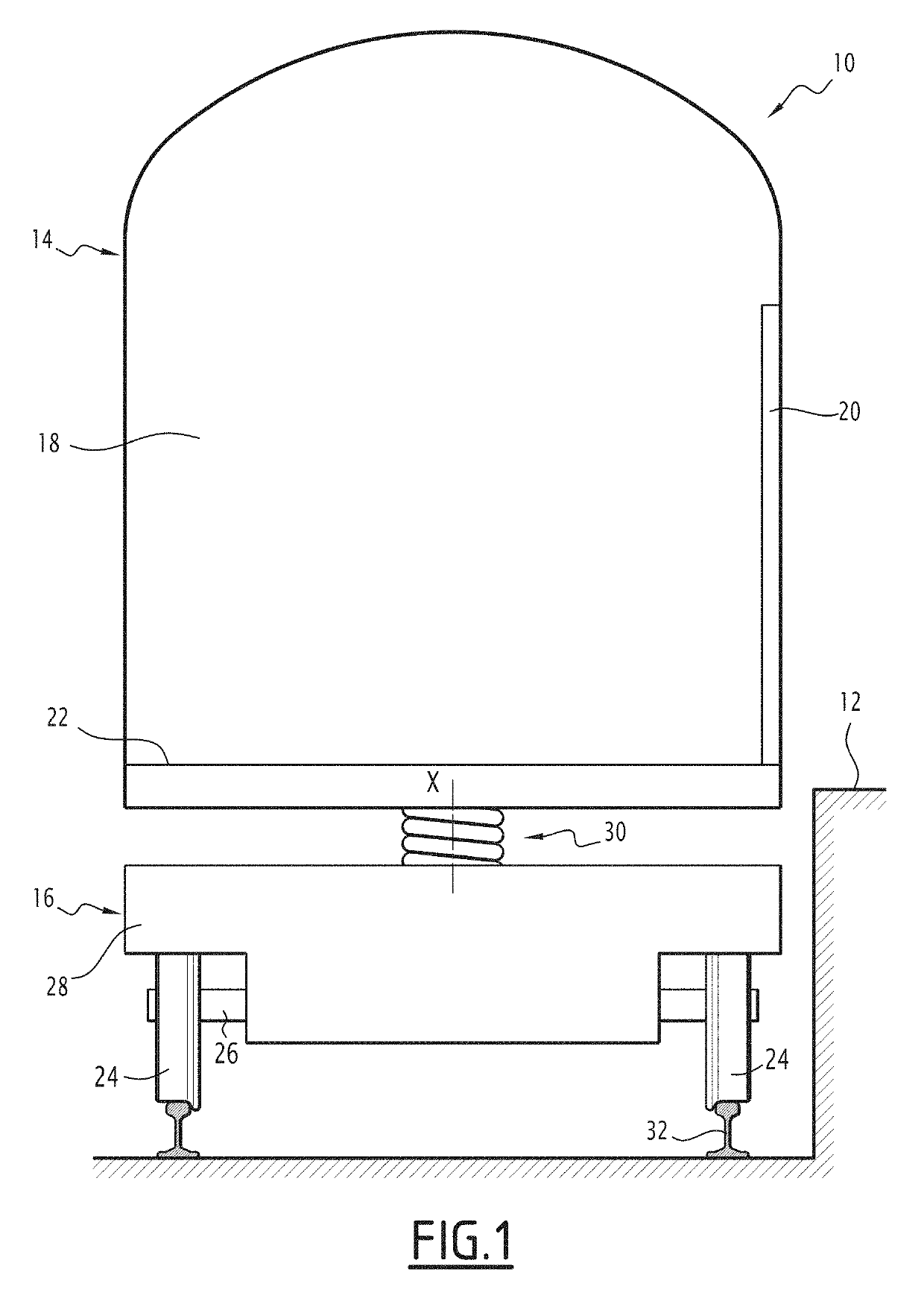
FIELD[0001]The present invention relates to a railway vehicle comprising at least one car and at least one bogie carrying the car, the bogie comprising a chassis and a secondary suspension system between the chassis and the car, the secondary suspension system comprising a jack comprising two ends extending along a same axis and a supply system of the jack.BACKGROUND[0002]In order to facilitate the embarking and disembarking of persons and / or goods, it is advantageous to be able to adjust the height of the car, in order to adapt it to that of the platform when the railway vehicle is at a station.[0003]Document US 2004 / 0016361 describes a rail vehicle comprising a car, a bogie and a suspension system comprising a suspension spring and a jack in parallel extending between the car and the bogie. The jack makes it possible to vary the distance between the bogie and the car, the height of the car thus being variable. This in particular makes it possible to reduce the vertical distance be...

Claims


Application Information

Patent Timeline
IPC IPC(8): B61F5/14B61F5/10
CPCB61F5/10B61F5/144B61F5/245B61F5/24
Inventor CLAVIER, JÉRÉMY
Owner ALSTOM TRANSPORT TECH SAS
Learn More