Flow rate adjustment valve, and fluid control apparatus in which the flow rate adjustment valve is used

a flow rate adjustment valve and fluid control technology, applied in the direction of diaphragm valves, engines, instruments, etc., can solve the problems of requiring time and effort, and failing to take advantage of small-sized manual valves, and achieve the effect of small vertical dimension of the flow rate adjustment valv

Active Publication Date: 2019-10-17
FUJIKIN INC
View PDF0 Cites 3 Cited by
  • Summary
  • Abstract
  • Description
  • Claims
  • Application Information

AI Technical Summary

Benefits of technology

[0025]In accordance with the flow rate adjustment valve of the present invention, because it is possible to make the vertical dimension of the flow rate adjustment valve small and to make the size of the motor per se small, it becomes possible to make the size of the flow rate adjustment valve, in which the motor is used, approximately equal to that of the manual valve type.
[0026]This flow rate adjustment valve is, therefore, applicable to a fluid control apparatus in which the flow rate adjustment valve of the manual valve type is being used and in which the space for the flow rate adjustment valve cannot be enlarged.

Problems solved by technology

This procedure has to be followed for all the fluid control apparatuses installed in the manufacturing line, which is a troublesome work requiring time and effort and fails to take advantage of using small-sized manual valves.

Method used


Image

  • Flow rate adjustment valve, and fluid control apparatus in which the flow rate adjustment valve is used
  • Flow rate adjustment valve, and fluid control apparatus in which the flow rate adjustment valve is used
  • Flow rate adjustment valve, and fluid control apparatus in which the flow rate adjustment valve is used

Examples


Embodiment Construction

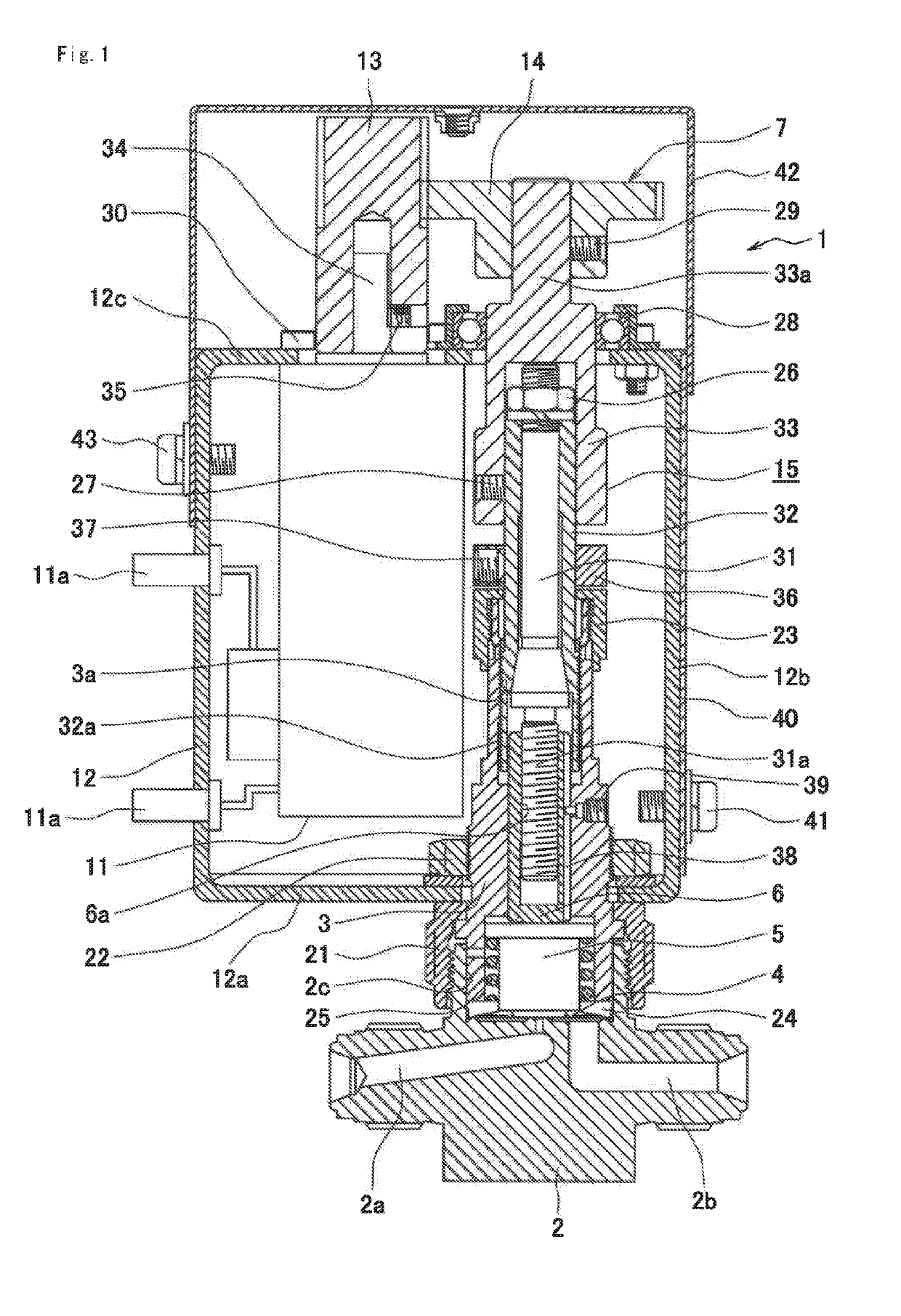
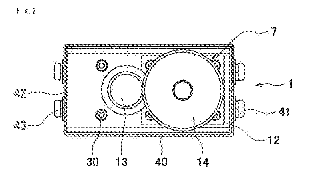
[0044]Embodiments of the present invention will be described below with reference to the drawings. In the following description, the upper and lower sides and the left and right sides of FIG. 1 are referred to as “upper” and “lower” sides and “left” and “right” sides, respectively. Moreover, the upper and lower sides of FIG. 2 are referred to as “front” and “rear” sides, respectively. These terms “upper”, “lower”, “left”, “right”, “front”, and “rear” are used for convenience's sake . For an actual use, a flow rate adjustment valve of the present invention may be used as appropriate so as to be arranged upside down, or so as to be arranged with the vertical direction thereof being directed horizontally.

[0045]As shown in FIG. 1, a flow rate adjustment valve 1 includes: a blocklike body 2 having a fluid inflow passage 2a, a fluid outflow passage 2b, and a recess 2c that is open upward;

[0046]a tubular bonnet 3 having a lower end portion screwed in an upper portion of the recess 2c of th...


PUM


Abstract

Provided is a flow rate adjustment valve of a motor-operated valve type, which overcomes the problems that flow rate adjustment valves of a manual valve type have, while making full use of compactness the manual valves have. The flow rate adjustment valve includes a rotation device that rotates a rotation member to cause a vertically movable body to move vertically. The rotation device includes: a driven gear disposed at an upper end portion of the rotation member; and a motor that rotates a driving gear engaged with the driven gear. The motor, which is a stepping servo motor, is disposed below the driving gear and has a rotary shaft extending upward. The driving gear is fixed to an upper end portion of the rotary shaft.

Description

TECHNICAL FIELD[0001]The present invention relates to a flow rate adjustment valve, and a fluid control apparatus in which the flow rate adjustment valve is used.BACKGROUND ART[0002]The fluid control apparatus is an essential component for a semiconductor manufacturing line.[0003]The flow rate adjustment valve used in the fluid control apparatus has a structure in which a vertically movable body adjusts an opening degree of a fluid passage, the opening degree of the fluid passage being defined by an valve element, and a rotation member that is screwed on the vertically movable body is rotated, whereby the vertically movable body moves upward or downward, in order to achieve adjustment of the opening degree of the fluid passage, which opening being defined by the valve element.[0004]Regarding the rotation of the rotation member, one structure is configured to rotate the rotation member by turning a handle by hand (manual valve type), and another structure is configured to rotate the ...

Claims


Application Information

Patent Timeline
Patent Type & Authority Applications(United States)
IPC IPC(8): F16K31/04F16K37/00G05D7/06F16K31/53
CPCF16K31/047F16K31/048G05D7/0635F16K37/00F16K31/53F16K31/046F16K31/508F16K7/16G05D7/06F16K31/04F16K31/54F16K37/0025
Inventor DOHI, RYOUSUKECHIBA, TAIJIWATANABE, KAZUNARI
Owner FUJIKIN INC
Why Eureka
Try Eureka