Antenna system with reduced multipath reception

a multi-path reception and antenna technology, applied in the direction of antennas, non-resonant long antennas, instruments, etc., can solve the problems of increasing the losses of the antenna feeder, the antenna is complex and large, and the signals of satellites near the horizon are the most vulnerable to distortion, so as to achieve a small vertical dimension and reduce the loss. , the effect of reducing the loss

Active Publication Date: 2017-03-07
TOPCON POSITIONING SYST INC
View PDF6 Cites 0 Cited by
  • Summary
  • Abstract
  • Description
  • Claims
  • Application Information

AI Technical Summary

Benefits of technology

[0007]To avoid undesirable shading of lower antenna elements by top elements, one embodiment proposes helical antennas as antenna elements.
[0009]The proposed antenna design provides the required suppression of multipath at a noticeably smaller dimension of the impedance ground plane compared to stand-alone antenna elements on the ground plane. The proposed structure has essentially fewer elements in comparison with a conventional vertical array and, therefore, a smaller vertical dimension. The feeder lines therefore have smaller length and correspondingly less losses and a greater efficiency.

Problems solved by technology

Signals from the satellites near the horizon are most vulnerable to distortions.
This leads to a complex structure and a large vertical dimensions of the antenna.
Moreover, there is an increase in losses in the antenna feeder, and a reduction of the antenna radiation efficiency.

Method used


Image

  • Antenna system with reduced multipath reception
  • Antenna system with reduced multipath reception
  • Antenna system with reduced multipath reception

Examples


Embodiment Construction

[0030]Reference will now be made in detail to the preferred embodiments of the present invention, examples of which are illustrated in the accompanying drawings.

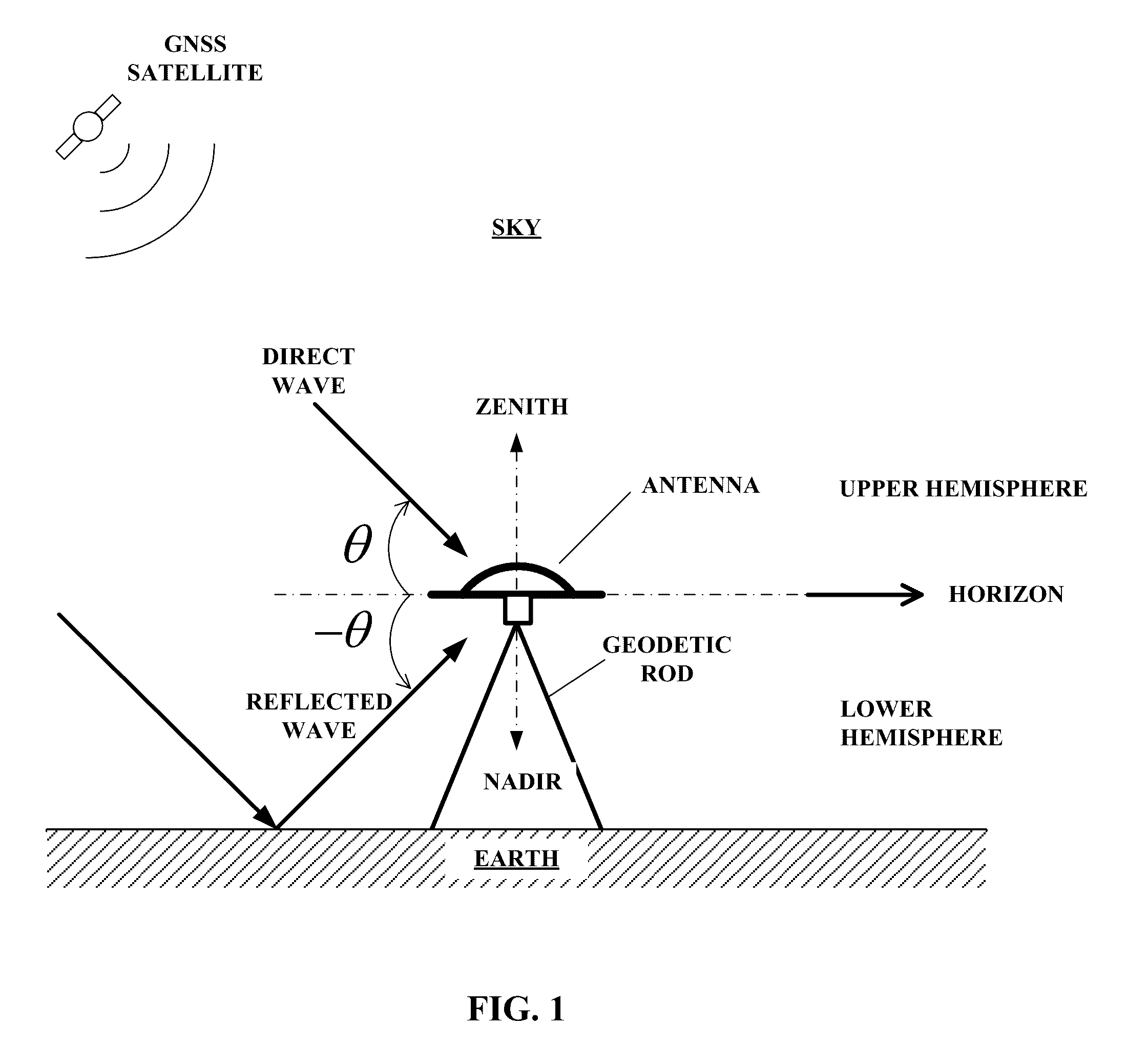
[0031]Navigation signals are received from satellites in the upper hemisphere up to elevation angles no more than 10° . . . 15° from the horizon. The signal reflected from the Earth's surface comes to the antenna from the side of the lower hemisphere. A conditional division of the space into upper (front) and lower (backward) hemispheres, and a schematic representation of incident and reflecting waves, is shown in FIG. 1. To provide reception of both navigation signals in the entire upper hemisphere and suppression of signals reflected from the ground, the antenna needs a sharp directional pattern (DP) cut-off below the horizon is needed which is possible when the antenna has a sharp difference of DP in the horizon direction.

[0032]As the antenna system receives signals from satellites located at an arbitrary point of the upp...


PUM


Abstract

An antenna system with a sharp difference in directional pattern is intended for receiving GNSS signals. The antenna system includes at least two antenna elements located above a high-impedance capacitive ground plane, and a combining network. Antenna elements are spaced apart in vertical direction. The combining network provides subtraction of the signal reflected from the ground, the arrangement of antenna elements above the high-impedance capacitive ground plane making such subtraction efficient.

Description

BACKGROUND OF THE INVENTION[0001]The present invention relates to a GNSS antenna with reduced multipath reception capable of cutting-off signals reflected from the ground. These signals are an important source of errors, so the decrease in reflected signals can lead to a higher positioning accuracy. This is especially critical for differential correction base stations. Signals from the satellites near the horizon are most vulnerable to distortions. To efficiently reject near-horizon satellite signals reflected from the ground, a special shape of directional patterns (DP) is required.[0002]Different variants of such antennas are known, including vertical phase arrays, see, for example, U.S. Pat. No. 7,583,236, U.S. Pat. No. 5,534,882. Suppression of reflected signals is achieved by using a great number of radiators. This leads to a complex structure and a large vertical dimensions of the antenna. Moreover, there is an increase in losses in the antenna feeder, and a reduction of the a...

Claims


Application Information

Patent Timeline
Patent Type & Authority Patents(United States)
IPC IPC(8): H01Q1/36G01S19/22H01Q11/08G01S19/36H01Q3/44
CPCH01Q11/08G01S19/22G01S19/36H01Q3/446
Inventor ASTAKHOV, ANDREY VITALIEVICHTATARNIKOV, DMITRY VITALIEVICH
Owner TOPCON POSITIONING SYST INC
Why Eureka
Try Eureka