Automotive air conditioner

Inactive Publication Date: 2007-06-28
SHIROTA YUICHI +8
View PDF39 Cites 1 Cited by
  • Summary
  • Abstract
  • Description
  • Claims
  • Application Information

AI Technical Summary

Benefits of technology

[0039] Further, because it is unnecessary to provide blowing ducts on the front and rear sides of the

Problems solved by technology

This results in a decrease in the space within the dashboard P and thus makes it difficult to mount such a lateral layout air conditioner within the dashboard.
Consequently, those air ducts results in an increase in the overall length of the air conditioner.
This increase makes

Method used


Image

  • Automotive air conditioner
  • Automotive air conditioner
  • Automotive air conditioner

Examples


embodiment 1

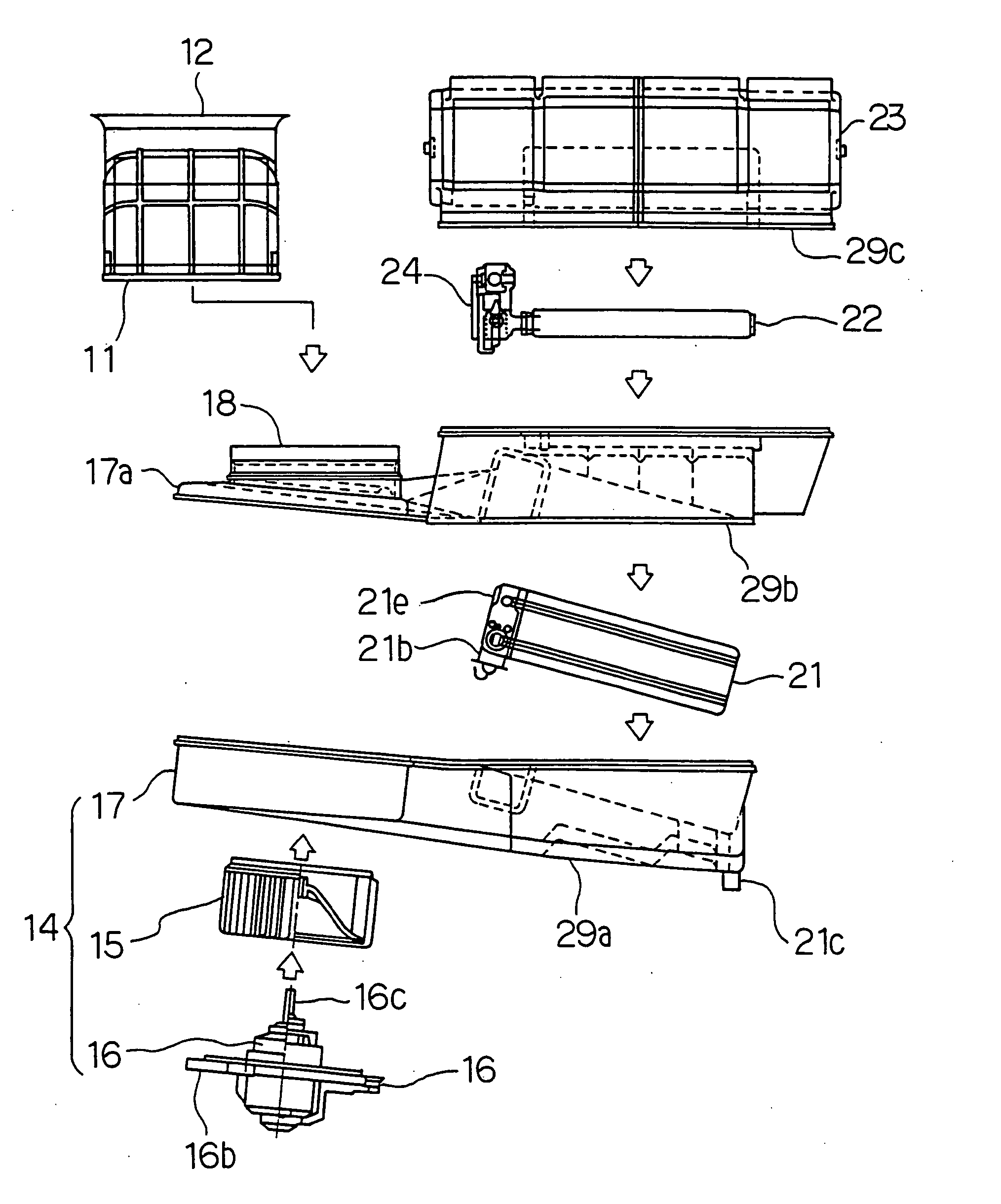
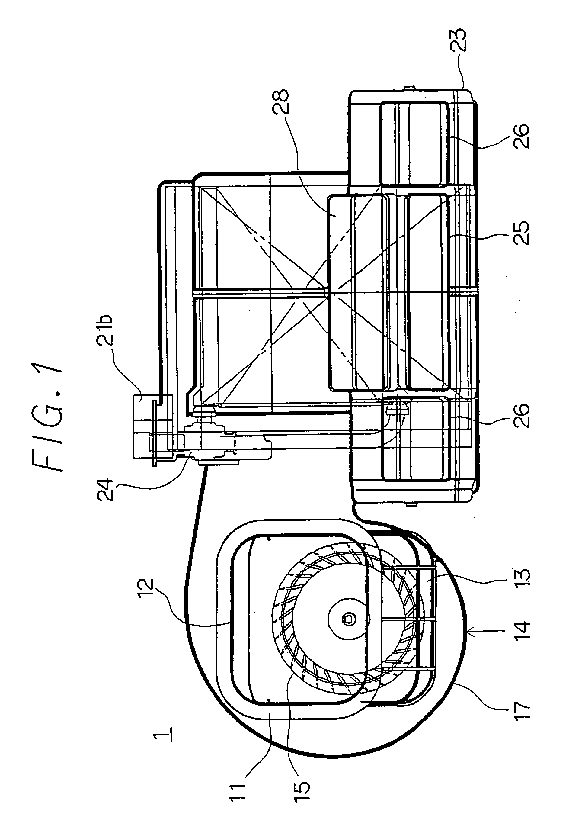
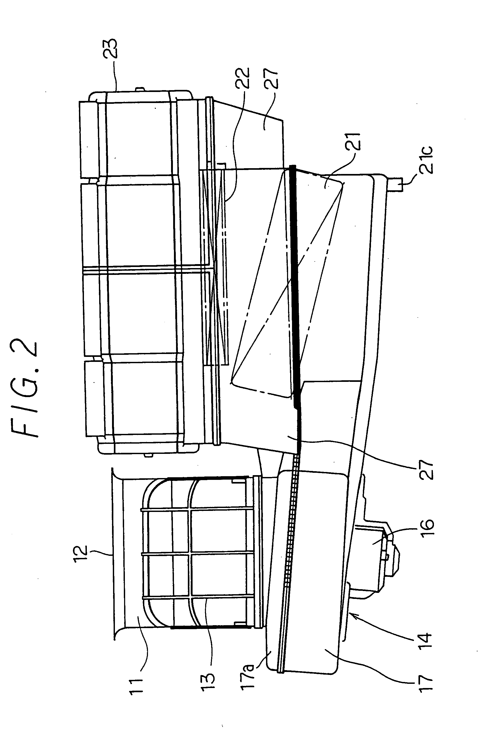
[0096] FIGS. 1 to 5 illustrate an automotive air conditioner according to a first embodiment of the present invention. Referring specifically to FIGS. 3 and 4, a vehicle includes an engine compartment A and a passenger compartment B. These compartments A and B are divided by a partition C (generally referred to as a “fire wall ” and made from an iron plate). A dashboard P is arranged within the passenger compartment B. The air conditioner comprises a fan unit 1 which is offset (to the left wheel the vehicle has a right steering wheel) from the central portion of the dashboard P in the width direction of the vehicle.

[0097] The fan unit 1 has an internal air / external air selector housing 11 arranged at its top and adapted to allow for selective introduction of internal and external airs. The internal air / external air selector housing 11 includes an external air inlet 12 and internal air inlets 13. An internal air / external air selector door (not shown) is mounted within the internal a...

embodiment 2

[0140] Referring to FIGS. 12A and 12B, the guide plate 21k has a cross shape to improve drainage of the condensed water. Specifically, the cross-shaped guide plate 21k has a flange 210k to stop the flow of the air and prevent upward flow of the air behind the flange 210k.

[0141] By this arrangement, the condensed water can more easily drop behind the flange 210k for better drainage. As an alternative, the guide plate 21k may have a T-shape to facilitate drainage of the condensed water.

[0142]FIG. 13 shows effects of the second embodiment. The vertical axis indicates the flow of air when 12 volts are applied to the fan motor 16 (see FIG. 5). The horizontal axis indicates the angle of inclination of the evaporator 21 with respect to a horizontal plane.

[0143] Referring to FIG. 13, the solid line shows the case in which the cross-shaped guide plates 21k of the second embodiment are provided. The broken line shows the case in which no cross-shaped guide plate 21k is provided.

[0144] As ...

embodiment 3

[0146] Referring to FIG. 14, the guide plates 21k are flat and inclined with respect to the direction of flow of the air. The guide plate 21k has a rear surface 211k. The upward flow of the air is retarded behind the rear surface 211k so as to allow the condensed water to easily drop behind the rear surface of each guide plate 21k.


PUM


Abstract

An automotive air conditioner comprises an offset blower for blowing an air, an evaporator is centrally disposed within a dashboard and receives the air from below, and a heater approximately horizontally disposed above the evaporator. The evaporator inclines downward along the direction of the air flow. A plurality of condensed water guide plates are provided under the evaporator so as to allow a condensed water smoothly flow on the surface of each guide plate and is discharged from the evaporator through a condensed water drain pipe.

Description

CROSS-REFERENCE TO RELATED APPLICATIONS [0001] This application is a divisional of U.S. patent application Ser. No. 09 / 531,531 filed on Mar. 21, 2000; which is a continuation of U.S. patent application Ser. No. 09 / 460,795 filed Dec. 15, 1999; which is a divisional of U.S. patent application Ser. No. 09 / 038,902 filed Mar. 12, 1995; which is a divisional of U.S. patent application Ser. No. 08 / 731,792 filed Oct. 18, 1996, now U.S. Pat. No. 5,755,107; which is a continuation-in-part of U.S. patent application Ser. No. 08 / 531,373 filed Sep. 21, 1995, now abandoned. This application claims the benefit of JP 7-281479 filed Oct. 30, 1995; JP 7-270148 filed Oct. 18, 1995; JP 7-235505 filed Sep. 13, 1995; JP 7-220903 filed Sep. 29, 1995; JP 6-240362 filed Oct. 4, 1994; and JP 6-227592 filed Sep. 22, 1994. The disclosures of the above applications are incorporated herein by reference.BACKGROUND OF THE INVENTION [0002] 1. Field of the Invention [0003] The present invention relates to an automot...

Claims


Application Information

Patent Timeline
IPC IPC(8): B60H3/00B60H1/00B61D27/00B60H1/32
CPCB60H1/00028B60H1/0005B60H1/00521B60H1/3233B60H2001/00078B60H2001/00092B60H2001/00107
Inventor SHIROTA, YUICHITANAKA, HISASHINONOYAMA, HIROSHISHIKATA, KAZUSHIUEMURA, YUKIOSUGI, HIKARUMIYATA, MANABUITO, KOJIKAMEOKA, TERUHIKO
Owner SHIROTA YUICHI
Why Eureka
Try Eureka