Mounting target working device

Active Publication Date: 2019-10-17
YAMAHA MOTOR CO LTD
View PDF0 Cites 0 Cited by
  • Summary
  • Abstract
  • Description
  • Claims
  • Application Information

AI Technical Summary

Benefits of technology

[0015]In the aforementioned structure in which the transfer unit includes the first transfer portion and the second transfer portion, the first transfer portion is preferably disposed at a different position from that of the first mounting target work area in the conveyance path. According to this structure, even in the conveyance path having a small arrangement space, spaces in which the first mounting target holder and the first transfer portion of the transfer unit are disposed can be easily ensured in the conveyance path.
[0016]In the aforementioned structure in which the transfer unit includes the first transfer portion and the second transfer portion, the first transfer portion is preferably disposed in the first mounting target work area of the conveyance path. According to this structure, as compared with the case in which the first transfer portion of the transfer unit and the first mounting target work area are disposed at different positions in the conveyance path, the conveyance path can be shortened, and thus the mounting target working device can be miniaturized accordingly.
[0017]In such a case, the first mounting target holder preferably includes a mounting target fixing unit that fixes the first mounting target when the head unit performs the operation on the first mounting target in the first mounting target work area, and in a state in which the mounting target fixing unit is retracted, the first transfer portion of the transfer unit preferably receives the second mounting target from the conveyance unit. According to this structure, when the first transfer portion of the transfer unit receives the second mounting target from the conveyance unit, the mounting target fixing unit of the first mounting target holder can be prevented from hindering the transfer operation.
[0018]In the aforementioned structure in which the transfer unit includes the first transfer portion and the second trans

Problems solved by technology

However, in the electronic component mounter described in Japanese Patent Laid-Open No. 2014-135416, it is only possible to perform work (mounting) on a mounting target having a simple

Method used


Image

  • Mounting target working device
  • Mounting target working device
  • Mounting target working device

Examples


Example

First Embodiment

[0039](Structure of Mounting Target Working Device)

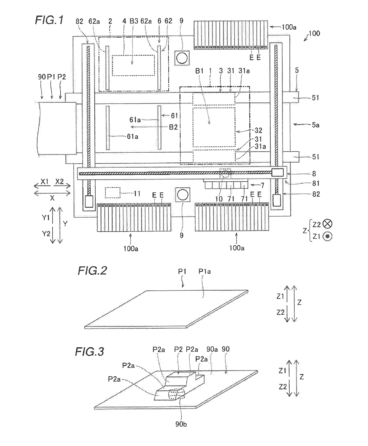
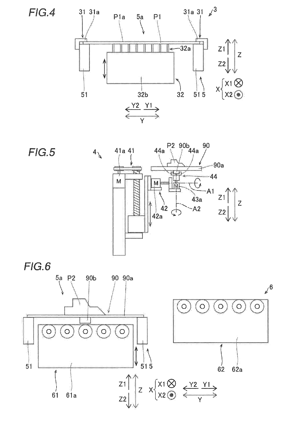
[0040]The structure of a mounting target working device 100 according to a first embodiment of the present disclosure is now described with reference to FIGS. 1 to 6.

[0041]In the first embodiment, as shown in FIG. 1, the mounting target working device 100 includes a first mounting target work area 1 (indicated by a two-dot chain line) in which an operation for mounting components E is performed by a head unit 7 described below on a first mounting target P1 (see FIG. 2) having a flat plate shape, and a second mounting target work area 2 (indicated by a two-dot chain line) in which the operation for mounting the components E is performed by the head unit 7 on a second mounting target P2 (see FIG. 3) having a three-dimensional shape as compared with the first mounting target P1. That is, the mounting target working device 100 is a component mounter capable of performing a mounting operation on both the first mounting ta...

Example

Second Embodiment

[0095]A second embodiment is now described with reference to FIGS. 15 and 16. In this second embodiment, an example in which a first transfer portion of a transfer unit is disposed in a first mounting target work area of a conveyance path unlike the aforementioned first embodiment is described. The same structures as those of the aforementioned first embodiment are denoted by the same reference numerals in the figures, and description thereof is omitted.

[0096](Structure of Mounting Target Working Device)

[0097]A mounting target working device 200 according to the second embodiment of the present disclosure differs from the mounting target working device 100 according to the aforementioned first embodiment in that the mounting target working device 200 includes a first mounting target holder 103, as shown in FIG. 15.

[0098]In the second embodiment, the first mounting target holder 103 is disposed at substantially the same position as a first transfer portion 61 of a tr...

Example

Third Embodiment

[0107]A third embodiment is now described with reference to FIG. 17. In this third embodiment, an example in which both a first mounting target work area and a second mounting target work area are disposed in a conveyance path unlike the aforementioned first and second embodiments is described. The same structures as those of the aforementioned first embodiment are denoted by the same reference numerals in the figures, and description thereof is omitted.

[0108](Structure of Mounting Target Working Device)

[0109]A mounting target working device 300 according to the third embodiment of the present disclosure differs from the mounting target working device 100 according to the aforementioned first embodiment in that a second mounting target holder 4 is disposed in a conveyance path 5a, and a transfer unit 6 is not provided, as shown in FIG. 17. Consequently, in the third embodiment, a second mounting target work area 202 is disposed in the conveyance path 5a, and a first ...


PUM


Abstract

A mounting target working device includes a head unit, a first mounting target work area in which the head unit mounts a component on a first mounting target having a flat plate shape, and a second mounting target work area in which the head unit mounts the component on a second mounting target having a three-dimensional shape as compared with the first mounting target.

Description

[0001]This application is a National Stage of International Patent Application No. PCT / JP2017 / 000275, filed Jan. 6, 2017, the entire content of which is incorporated herein by reference.BACKGROUNDTechnical Field[0002]The present disclosure relates to a mounting target working device.Background Art[0003]Conventionally, a mounting target working device that mounts components on a substrate is known. Such a mounting target working device is disclosed in Japanese Patent Laid-Open No. 2014-135416.[0004]Japanese Patent Laid-Open No. 2014-135416 discloses an electronic component mounter (mounting target working device) including a substrate conveyance unit that conveys a printed circuit board having a flat plate shape, and a component moving unit that mounts electronic components on the printed circuit board.SUMMARY[0005]In the technical field of an electronic component mounter as described in Japanese Patent Laid-Open No. 2014-135416, work such as mounting of components may be performed o...

Claims


Application Information

Patent Timeline
IPC IPC(8): H05K13/04H05K13/02H05K13/08H05K3/34H05K1/02H05K1/18H05K13/00
CPCH05K3/34H05K1/18H05K1/0284H05K13/02H05K13/0417H05K13/0061H05K13/0812H05K13/0408
Inventor KISHIDA, AKIRANOZUE, TOMOYUKI
Owner YAMAHA MOTOR CO LTD
Why Eureka
Try Eureka