Liquid crystal display apparatus

Active Publication Date: 2019-10-24
TRIVALE TECH
View PDF6 Cites 2 Cited by
  • Summary
  • Abstract
  • Description
  • Claims
  • Application Information

AI Technical Summary

Benefits of technology

The technical effect of this patent is to prevent damage to the liquid crystal panel and reduce display unevenness when a person touches it in a curved liquid crystal display apparatus.

Problems solved by technology

First of all, it is possible to say that the curved display of the type in which the organic EL panel is curved, which is the latter, is suitable for an application to the curved display since it is comparatively easy to form the organic EL panel using a flexible substrate such as a plastic substrate, but the number of manufacturers stably mass-producing curved displays is small because manufacture of the organic EL panel itself requires high cost and mass-production techniques therefor are not sufficiently established, and there is a problem in terms of reliability.
Particularly, curved displays that have problems in terms of reliability are not suitable due to the nature of products in automotive applications where the curved displays have been demanded in recent years.
On the other hand, in the curved display of the type in which the liquid crystal panel is curved, it is difficult to use a plastic substrate basically due to constraints such as heat-resistance with respect to processing temperature of a realistic manufacturing process, a positional shift, and the like of the liquid crystal panel.
For example, a curved display configured using a liquid crystal panel using a plastic substrate has been limitedly used for an application to perform relatively simple display of characters, figures, and the like such as a wristwatch application.
Such a glass substrate having a thickness of about 0.1 mm to 0.2 mm, as a matter of course, has extremely weak strength, and the strength of the liquid crystal panel configured using the thinned glass substrate is weak as a whole.
Particularly when the touch panel function is provided, it is assumed that a person touches a display surface of the display for a touch panel operation, an external pressure (external force: hereinafter referred to as surface pressing stress), applied as the person touches the surface of the liquid crystal panel constituted by such a thinned glass substrate, is applied, a technical problem such as damage of the liquid crystal panel occurs.
That is, even if there is a difference in degree, the curved displays of the type in which the liquid crystal panel is curved generally have the common technical problem that the liquid crystal panel constituted by the thinned glass substrate is easily damaged, which is a first major problem.
Further, as problems caused by the surface pressing stress being applied as a person touches the liquid crystal panel in the general curved displays of the type in which the liquid crystal panel is curved, not only the above-described damage is concerned but also a cell gap becomes narrow as the surface pressing stress is directly applied in a pressed portion even if the application of the surface pressing stress does not lead to the damage.
As a result, when the cell gap of the liquid crystal panel varies nonuniformly within a plane, display unevenness is visually recognized, and such generation of the display unevenness is also a problem that coexists with the damage of the liquid crystal panel itself.
As a result, the cell gap of the liquid crystal panel nonuniformly varies in the plane, which leads to the display unevenness.
The surface pressing stress is applied as the person touches the liquid crystal panel so that display unevenness occurs, which is a second major problem.
However, Japanese Patent Application Laid-Open No. 2007-272107 and Japanese Patent Application Laid-Open No. 2012-133428 do not focus on both the two major problems generated by the surface pressing stress applied as the person touches the liquid crystal panel in the above-described curved display of the type in which the liquid crystal panel is curved, and do not disclose a configuration or a method capable of collectively solving both the problems in a balanced manner.
Specifically, even if the configuration of Japanese Patent Application Laid-Open No. 2007-272107 is used, no solution is illustrated with respect to, for example, the direct action of the surface pressing stress generated by the surface pressing stress applied as the person touches the liquid crystal panel, the action by the holding stress generated by the housing, and the variation of the cell gap caused by the influence of the configuration inside the liquid crystal panel, and the accompanying display unevenness although countermeasures against the variation of the cell gap generated by the stress applied to the liquid crystal panel from the housing and the accompanying display unevenness are taken with respect to the two major problems.
However, a holding mode using the housing of the liquid crystal panel is not specifically illustrated, for example, and thus, a stress held by the housing is applied to the back side of the liquid crystal panel when being pressed from the front side in the case of holding the back side of the liquid crystal panel with the housing so that there is a concern that the liquid crystal panel may be damaged from the back side.
Further, similarly to Japanese Patent Application Laid-Open No. 2007-272107, no solution is illustrated for the action of holding stress generated by the housing, and the variation of the cell gap caused by the influence of the configuration inside the liquid crystal panel and accompanying display unevenness, although the action of mitigating the variation of the cell gap caused by the direct action of the surface pressing stress on the liquid crystal panel is expected.

Method used


Image

  • Liquid crystal display apparatus
  • Liquid crystal display apparatus
  • Liquid crystal display apparatus

Examples


first preferred embodiment

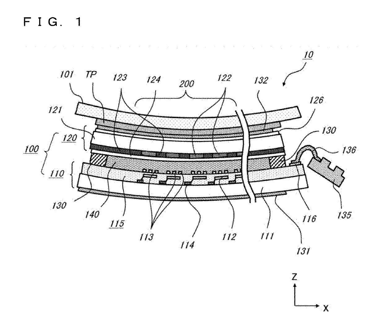
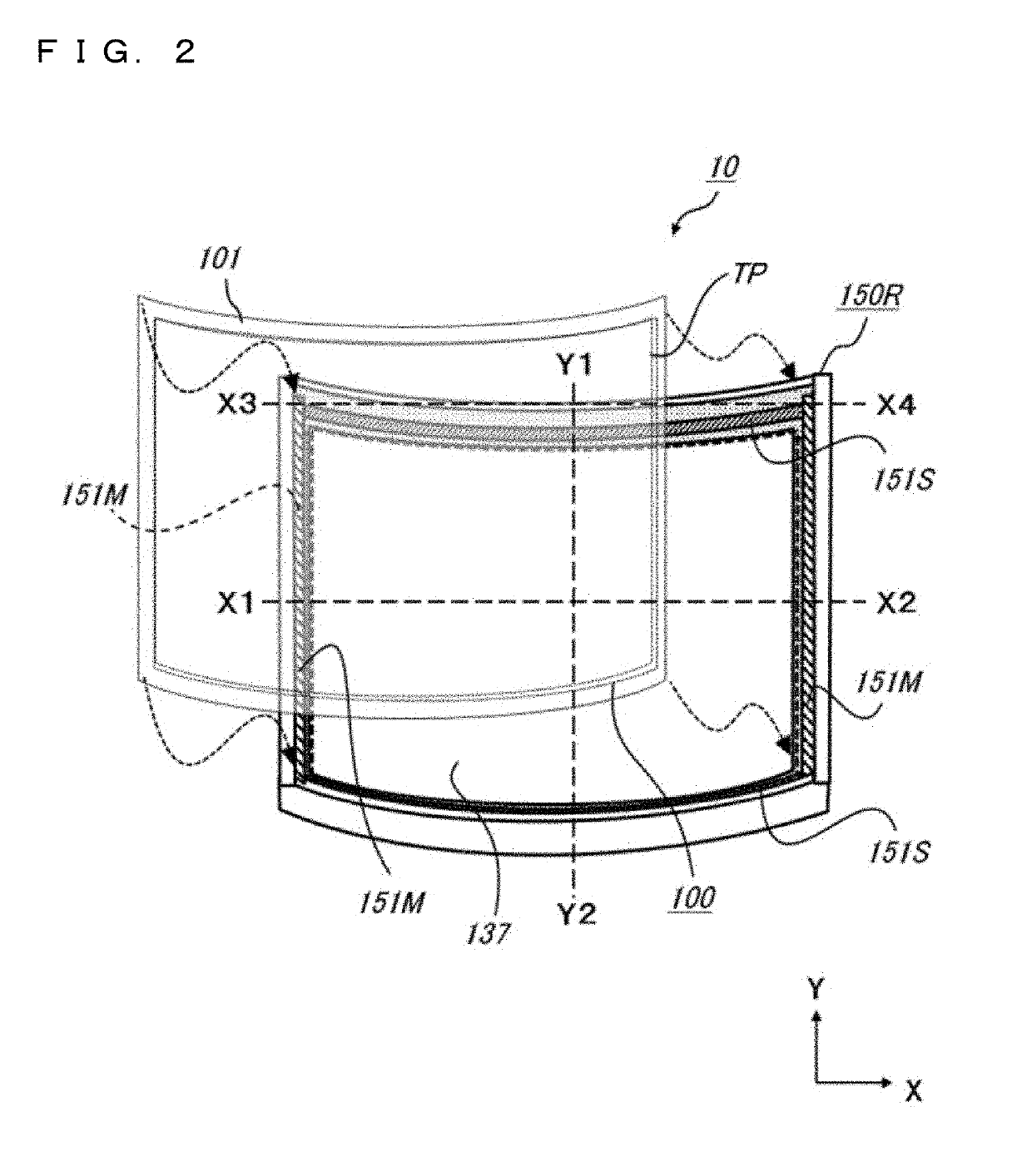
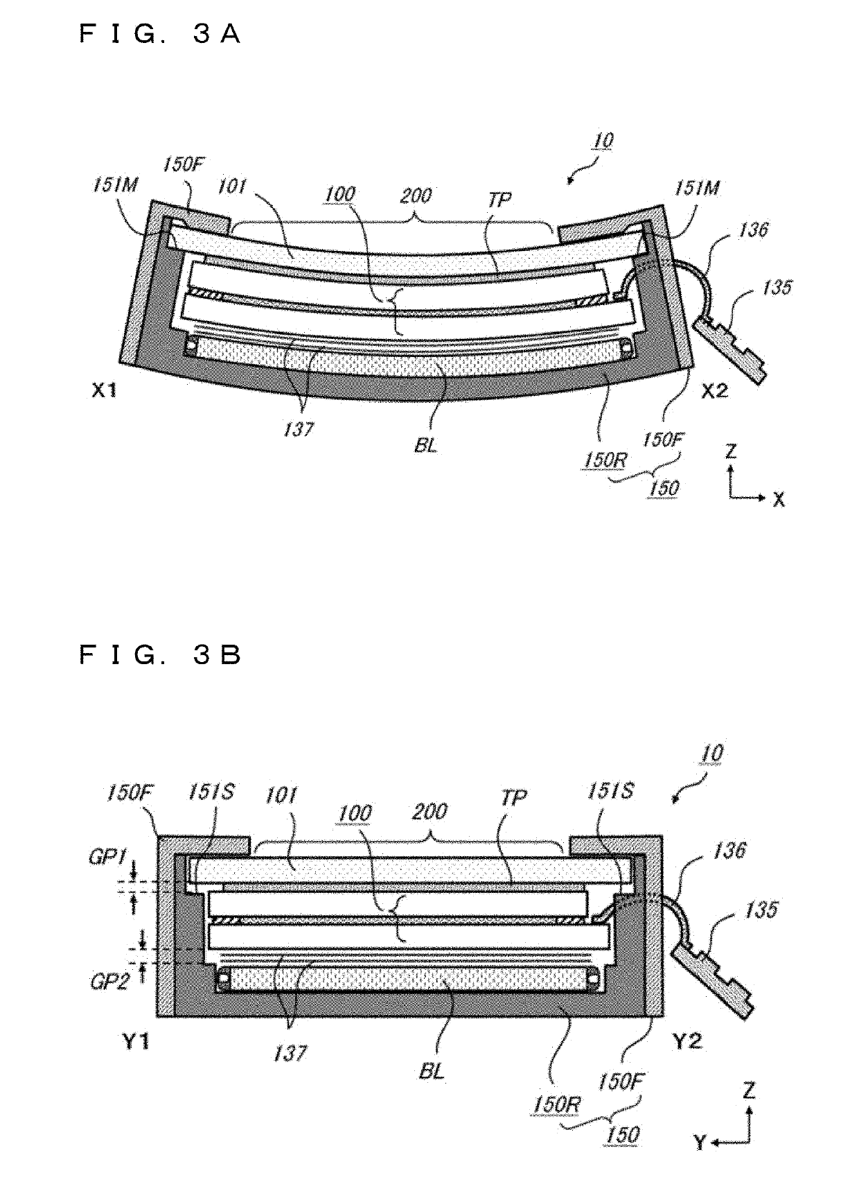
[0045]A description will be given regarding a configuration of a curved display of a first preferred embodiment which is a curved liquid crystal display apparatus including a curved liquid crystal panel, the liquid crystal display apparatus of the first preferred embodiment which is an example to which the present invention is applied with reference to FIGS. 1 to 7B. FIG. 1 is a schematic diagram illustrating a cross-sectional view of an overall configuration of a liquid crystal panel 100 forming a curved display 10. FIGS. 2 to 3B are explanatory views illustrating an overall configuration of the curved display 10 and particularly illustrating a mode of holding the curved display 10 by a housing of the liquid crystal panel 100 which is one main part of the present invention. FIG. 2 illustrates an overall view of the liquid crystal panel 100 and the housing holding the liquid crystal panel 100, FIG. 3A corresponds to a cross-sectional view in a direction along a curve direction (a vi...

second preferred embodiment

[0139]Next, a description will be given regarding a configuration and an operation of a curved display 10a as a liquid crystal display apparatus according to a second preferred embodiment, which is a modification particularly relating to a holding mode using a housing of the curved display 10 of the first preferred embodiment, with reference to FIGS. 14A to 15C. Here, FIGS. 14A to 15C are cross-sectional views illustrating a state corresponding to presence or absence of application of the surface pressing stress FS to a display surface side of the liquid crystal panel 100 in the curved display 10a of the second preferred embodiment, and correspond to FIGS. 9A to 10C used in the description on the operation of the first preferred embodiment. Similarly to the respective cross-sectional views in FIGS. 9A to 10C, FIGS. 14A and 15A correspond to the cross-sectional views in a direction along a curve direction (a vicinity of a central portion), FIGS. 14B and 15B correspond to the cross-se...

third preferred embodiment

[0147]Next, a description will be given regarding a configuration and an operation of a curved display 10b as a liquid crystal display apparatus according to a third preferred embodiment, which is a modification particularly relating to a holding mode using a housing of the curved display 10 of the first preferred embodiment, with reference to FIGS. 16 to 18C. Here, FIG. 16 illustrates an overall view of a liquid crystal panel 100 included in the curved display 10b of the third preferred embodiment and a housing holding the liquid crystal panel 100, and corresponds to FIG. 2 according to the first preferred embodiment. In addition, FIGS. 17A to 18C are cross-sectional views illustrating a state corresponding to presence or absence of application of the surface pressing stress FS to a display surface side of the liquid crystal panel 100 in the curved display 10b, and correspond to FIGS. 9A to 10C used in the description on the operation of the first preferred embodiment. Similarly to...


PUM


Abstract

A liquid crystal display apparatus of the present invention includes a housing holding an outer peripheral portion of a liquid crystal panel with gap portions provided in a central portion thereof such that a curvature of a curved shape is variable when a surface pressing stress is applied, in which columnar spacers are arranged at a higher density in a region of the central portion in a curve direction than in a region of a peripheral portion, the density being the density of the columnar spacers holding a gap between glass substrates in a display region of the curved liquid crystal panel.

Description

BACKGROUND OF THE INVENTIONField of the Invention[0001]The present invention relates to a liquid crystal display apparatus, and particularly to a curved liquid crystal display apparatus including a curved liquid crystal panel.Description of the Background Art[0002]From the viewpoint of designability and space saving, the necessity of a curved display apparatus (also referred to as a curved display), which is a display apparatus having a curved display screen, has increased. As a form of this curved display, there are a type of using a liquid crystal display apparatus (also referred to as a liquid crystal display) in which a liquid crystal panel forming the liquid crystal display is curved, a type of using an organic EL display apparatus (also referred to as an organic EL display) in which an organic EL panel forming the organic EL display is curved, and the like.[0003]First of all, it is possible to say that the curved display of the type in which the organic EL panel is curved, whi...

Claims


Application Information

Patent Timeline
IPC IPC(8): G02F1/1333G02F1/1339
CPCG02F1/13338G02F1/133305G02F1/1339G02F1/133308G02F1/133322G02F1/133331G02F1/13398
Inventor KUDO, YUKIHIROYONEMURA, KOJIUMEDA, HIROSHI
Owner TRIVALE TECH
Why Eureka
Try Eureka