Systems and methods for fabricating microfluidic devices

a technology of microfluidic devices and systems, applied in the field of systems and methods for fabricating microfluidic devices, can solve the problems of complex devices that are unfavorable or difficult to implement by other means of manufacturing, and achieve the effects of reducing manufacturing costs, simplifying the overall development of microfluidic devices, and increasing process yields

Active Publication Date: 2019-10-31
CHARLES STARK DRAPER LABORATORY
View PDF0 Cites 2 Cited by
  • Summary
  • Abstract
  • Description
  • Claims
  • Application Information

AI Technical Summary

Benefits of technology

[0009]Solid freeform fabrication processes, such as 3D printing, are used to produce devices capable of ex vivo simulation of the dynamics of cell-tissue interactions. Advantages of this approach include the ability to monolithically integrate various features, including tissue capture regions, cell flow channels, resistance lines and fluidic connections, and bubble traps, rather than assembling components in a manner that runs the risk of introducing flow anomalies at connection points that may generate bubbles or sequester or damage flowing cells. Additive manufacturing (AM), i.e., the layer-by-layer creation of solid objects, using as a template, a computer-aided design (CAD) file, is a promising approach for implementing microfluidic systems. Accessibility of printing technologies and availability of printable materials that exhibit diverse mechanical, chemical, and optical properties make AM practical for many applications and user-experience levels. In addition to greater flexibili

Problems solved by technology

Advantages of this approach include the ability to monolithically integrate various features, including tissue capture regions, cell flow channels, resistance lines and fluidic connections, and bubble traps, rather than assembling components in a manner that runs the risk of introducing flow anomalies at

Method used


Image

  • Systems and methods for fabricating microfluidic devices
  • Systems and methods for fabricating microfluidic devices
  • Systems and methods for fabricating microfluidic devices

Examples


Embodiment Construction

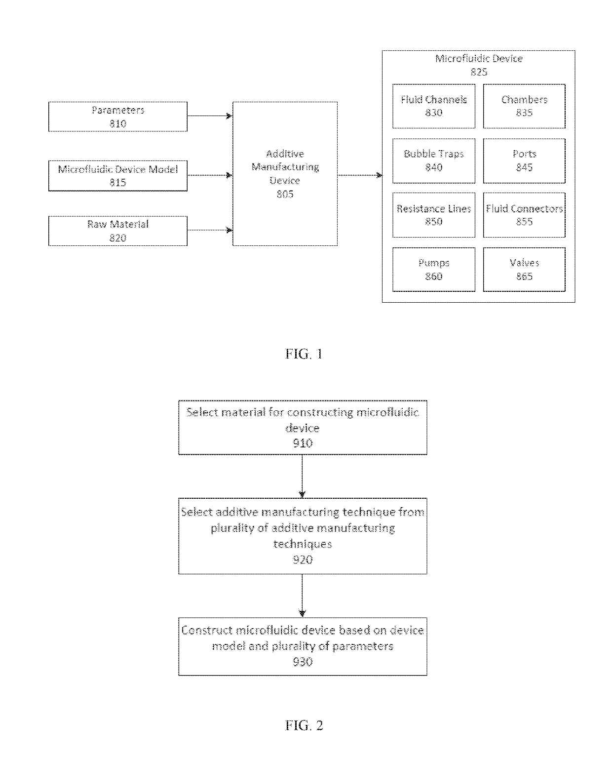
[0023]Additive manufacturing (AM), i.e., the layer-by-layer creation of solid objects, using as a template, a computer-aided design (CAD) file, is a promising approach for implementing microfluidic systems. Accessibility of printing technologies and availability of printable materials that exhibit diverse mechanical, chemical, and optical properties make AM practical for many applications and user-experience levels. In addition to greater flexibility in the types of component geometries that can be created, AM simplifies the overall development of microfluidic devices and increases process yields. The potential for monolithic construction of a 3D-printed microfluidic device eliminates the need for subsequent adhesion or bonding processes, improving the consistency of its manufacturing by eliminating the need for alignment and by limiting operator involvement and potentially error in the fabrication. The true 3D capabilities also permit curved fluidic transitions and minimized dead v...


PUM

PropertyMeasurementUnit
Fractionaaaaaaaaaa
Fractionaaaaaaaaaa
Fractionaaaaaaaaaa

Abstract

This disclosure describes techniques for fabricating a high-resolution, non-cytotoxic and transparent microfluidic device. A material can be selected based on having an optical property with a predetermined degree of transparency to provide viewability of a biological sample through the microfluidic device and a level of cytotoxicity within a predetermined threshold to provide viability of the biological sample within the microfluidic device. An additive manufacturing technique can be selected from a plurality of additive manufacturing techniques for fabricating the microfluidic device based on the selected material to provide a resolution of dimensions of one or more channels of the microfluidic device higher than a predetermined resolution threshold.

Description

CROSS-REFERENCE TO RELATED APPLICATIONS[0001]The present application claims priority to U.S. Provisional Patent Application 62 / 552,267, filed Aug. 30, 2017 and titled “SYSTEMS AND METHODS FOR 3D PRINTING FABRICATION OF MICROFLUIDIC TISSUE BIOPSY DEVICES,” to U.S. Provisional Patent Application 62 / 611,513, filed Dec. 28, 2017 and titled “SYSTEMS AND METHODS FOR 3D PRINTING FABRICATION OF MICROFLUIDIC TISSUE BIOPSY DEVICES,” and to U.S. Provisional Patent Application 62 / 649,016, filed Mar. 28, 2018 and titled “SYSTEMS AND METHODS FOR FABRICATING MICROFLUIDIC DEVICES,” each of which is incorporated herein by reference in its entirety.FIELD OF THE DISCLOSURE[0002]The present disclosure is generally in the field of improved materials for use in making microfluidics devices using techniques such as 3D printing or DLP-SLA, the materials being biocompatible, producing high resolution features, high transparency to visible light, and low to no autofluorescence.BACKGROUND OF THE DISCLOSURE[00...

Claims


Application Information

Patent Timeline
IPC IPC(8): B01L3/00B81C1/00B29C64/135B29C64/393
CPCB81C1/00071B01L3/502707B01L2200/12B81B2203/0338B81B2201/058B29C64/135B33Y10/00B29C64/393B33Y80/00B01L2200/10B01L2300/0861B01L2300/123B81C1/00119Y10T428/24744
Inventor BECKWITH, ASHLEY LYNNEBORENSTEIN, JEFFREYMOORE, NATHANDOTY, DANIELVELASQUEZ-GRACIA, LUIS
Owner CHARLES STARK DRAPER LABORATORY
Why Eureka
Try Eureka