
Rotary coating tool

a technology of rotary tool and coating surface, which is applied in the direction of coating, molten spray coating, metallic material coating process, etc., can solve the problems of not disclosing the rotating part, the propensity of thermal spray methods to overheat the bore and the part forming the bore, and the bore not disclosing the entire surface of the bore, etc., to achieve simplified and economical rotary tool, no need to rotate the part, and low temperature operation

Inactive Publication Date: 2019-10-31
INNOVATION TECH INC
View PDF3 Cites 0 Cited by
  • Summary
  • Abstract
  • Description
  • Claims
  • Application Information

AI Technical Summary

Benefits of technology

The invention is a mounting structure that allows a rotary tool to be attached to a robot or gantry without the need to rotate the parts being coated. This reduces the risk of thermal degradation and allows for continuous coating of bores and internal surfaces without the need for heavy parts. The mounting structure also allows for low temperature operation and no-need-to-rotate coating of internal surfaces or bores of parts. Overall, the invention is a simplified and economical way to coat parts.

Problems solved by technology

These patents do not disclose rotating the part.
But, this method has disadvantages including the propensity of the thermal spray methods used to overheat the bore and the part forming the bore.
But, Payne does not disclose coating the entire surface of small diameter bores by rotating the cold spray nozzle.

Method used


Image

  • Rotary coating tool
  • Rotary coating tool
  • Rotary coating tool

Examples


Embodiment Construction

[0035]The disclosure provided in the following pages describes examples of some embodiments of the invention. The designs, figures, and description are non-limiting examples of the embodiments they disclose. For example, other embodiments of the disclosed device and / or method may or may not include the features described herein. Moreover, described features, advantages or benefits may apply to only certain embodiments of the invention and should not be used to limit the disclosed invention.

[0036]As used herein, the term “coupled” includes direct and indirect connections. Moreover, where first and second devices are coupled, intervening devices including active devices may be located therebetween.

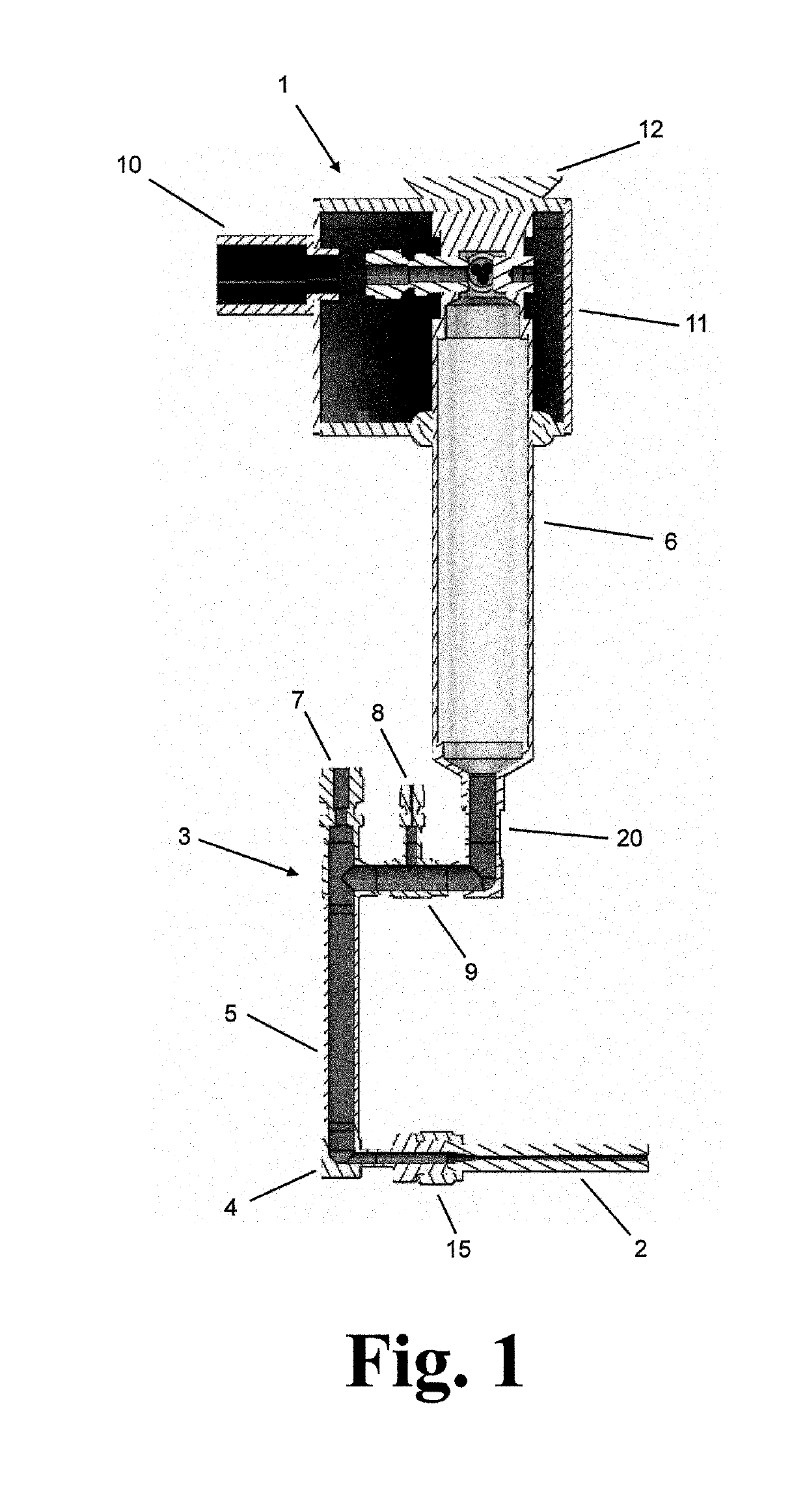
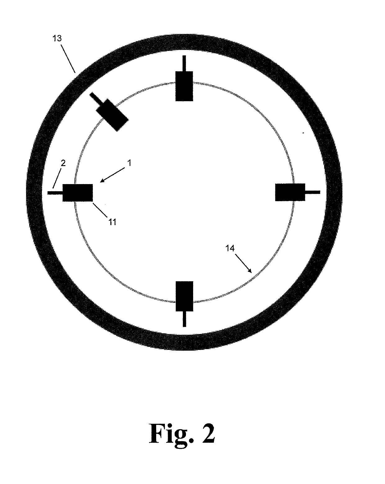
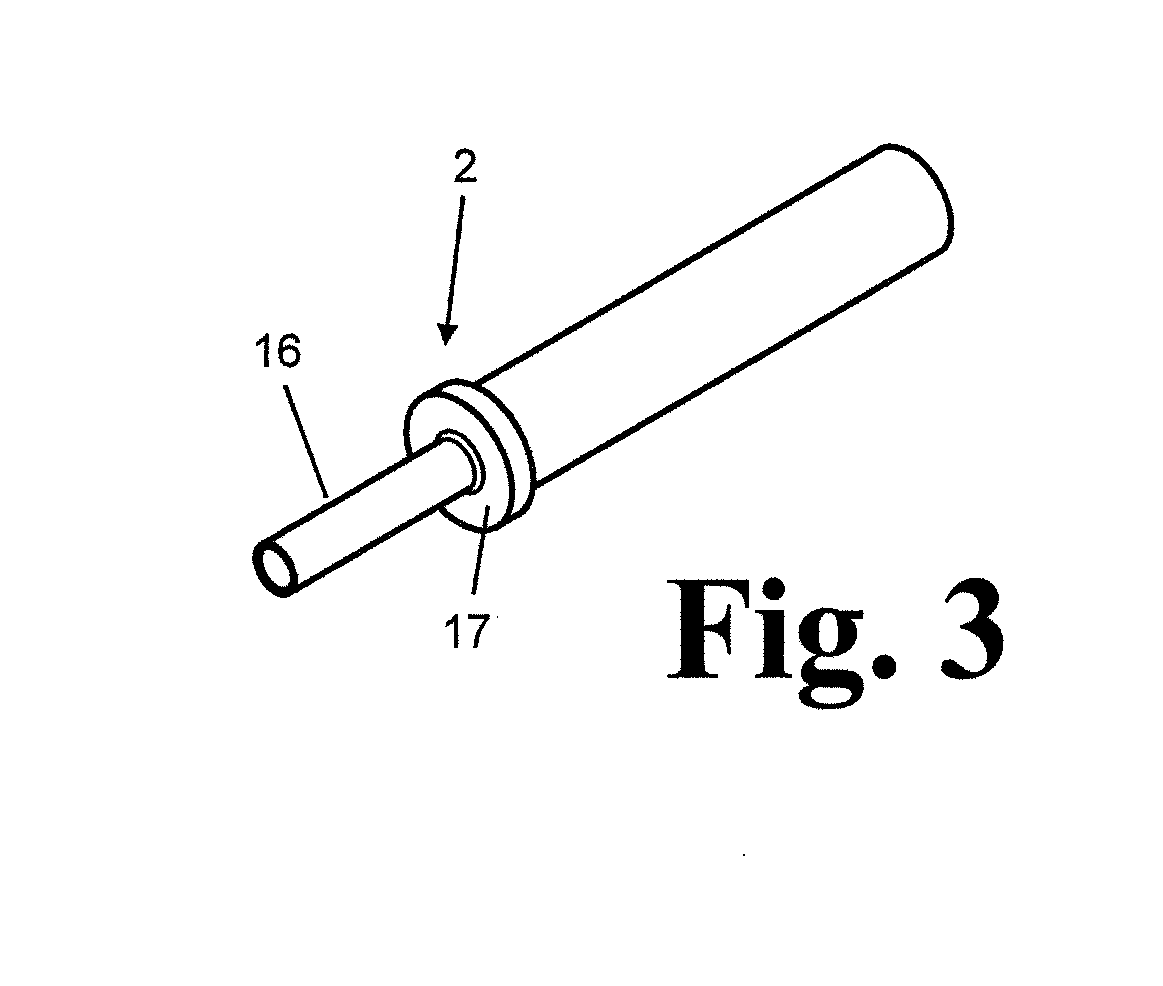
[0037]FIG. 1 shows the preferred embodiment of the rotary tool (1) for coating or additively manufacturing the surface of a part. The tool comprises a modified nozzle such as a friction compensated sonic nozzle (2) as disclosed in U.S. Pat. No. 6,915,964. The nozzle is connected to a nozzle ...


PUM

PropertyMeasurementUnit
degrees of freedomaaaaaaaaaa
temperatureaaaaaaaaaa
standoff distanceaaaaaaaaaa

Abstract

A rotary coating tool includes a rotary tool for coating bores and surfaces using solid-state deposition and consolidation of high velocity powder particles undergoing thermal plastic deformation.

Description

INCORPORATION BY REFERENCE[0001]This application incorporates by reference in its entirety and for all purposes the disclosure of U.S. Pat. No. 6,915,964 B2 filed Apr. 5, 2002 and issued Jul. 12, 2005.BACKGROUND OF THE INVENTIONField of the Invention[0002]The present invention relates to a rotary coating tool. Uses of the tool include coating or additively manufacturing the surface of a part (“part”). The part may be stationary and the rotary tool for coating or additively manufacturing may be rotated around the internal or external surfaces of the part.[0003]Exemplary part surfaces are flat, curved, cylindrical, interior, or exterior surfaces. For example, the part surface may be a cylindrical bore or a cylindrical bore having a particular depth. Part surfaces may take any shape, for example a cylindrical shape that is the interior or exterior of a cylindrical part.[0004]The rotary tool comprises nozzles such as a modified friction compensated sonic nozzle similar to the nozzle dis...

Claims


Application Information

Patent Timeline
Patent Type & Authority Applications(United States)
IPC IPC(8): B05B3/02C23C4/12B05B7/14B05B7/16B05B7/22
CPCC23C4/12B05B7/144B05B7/1626B05B3/028B05B7/168B05B7/22B05B13/0431B05B13/0636C23C24/04
Inventor TAPPHORN, RALPHGABEL, HOWARD
Owner INNOVATION TECH INC
Learn More