Force sensor and manufacture method thereof

Active Publication Date: 2019-10-31
MIRAMEMS SENSING TECH
View PDF4 Cites 7 Cited by
  • Summary
  • Abstract
  • Description
  • Claims
  • Application Information

AI Technical Summary

Benefits of technology

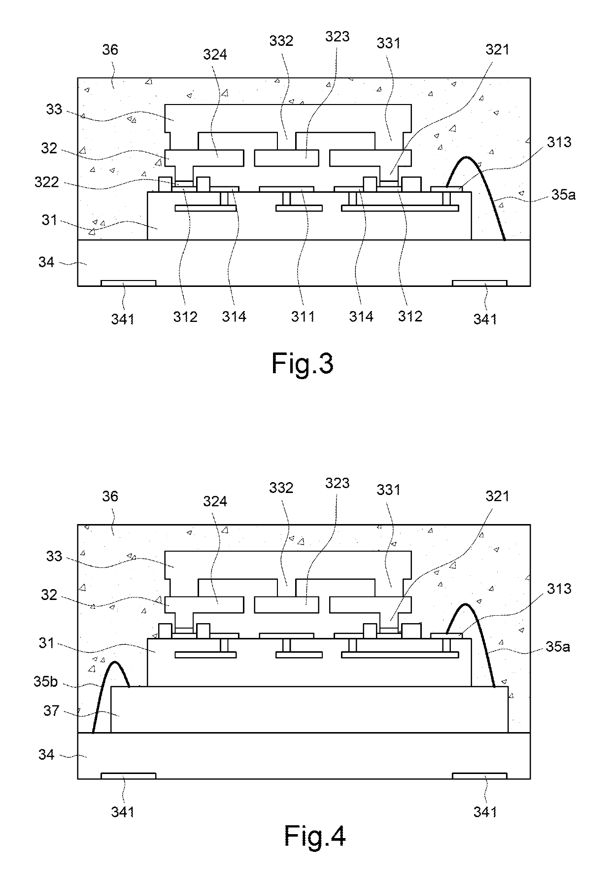
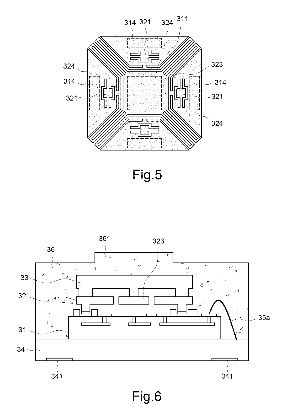
[0005]The present invention provides a force sensor and a manufacture method thereof, wherein a third substrate is disposed between a package body and a MEMS element to function as the cover of the MEMS element, and wherein the MEMS element is connected with the cover and generates a movement corresponding to the deformation of the cover, whereby the leads inside the force sensor are far away from the stress source gene

Problems solved by technology

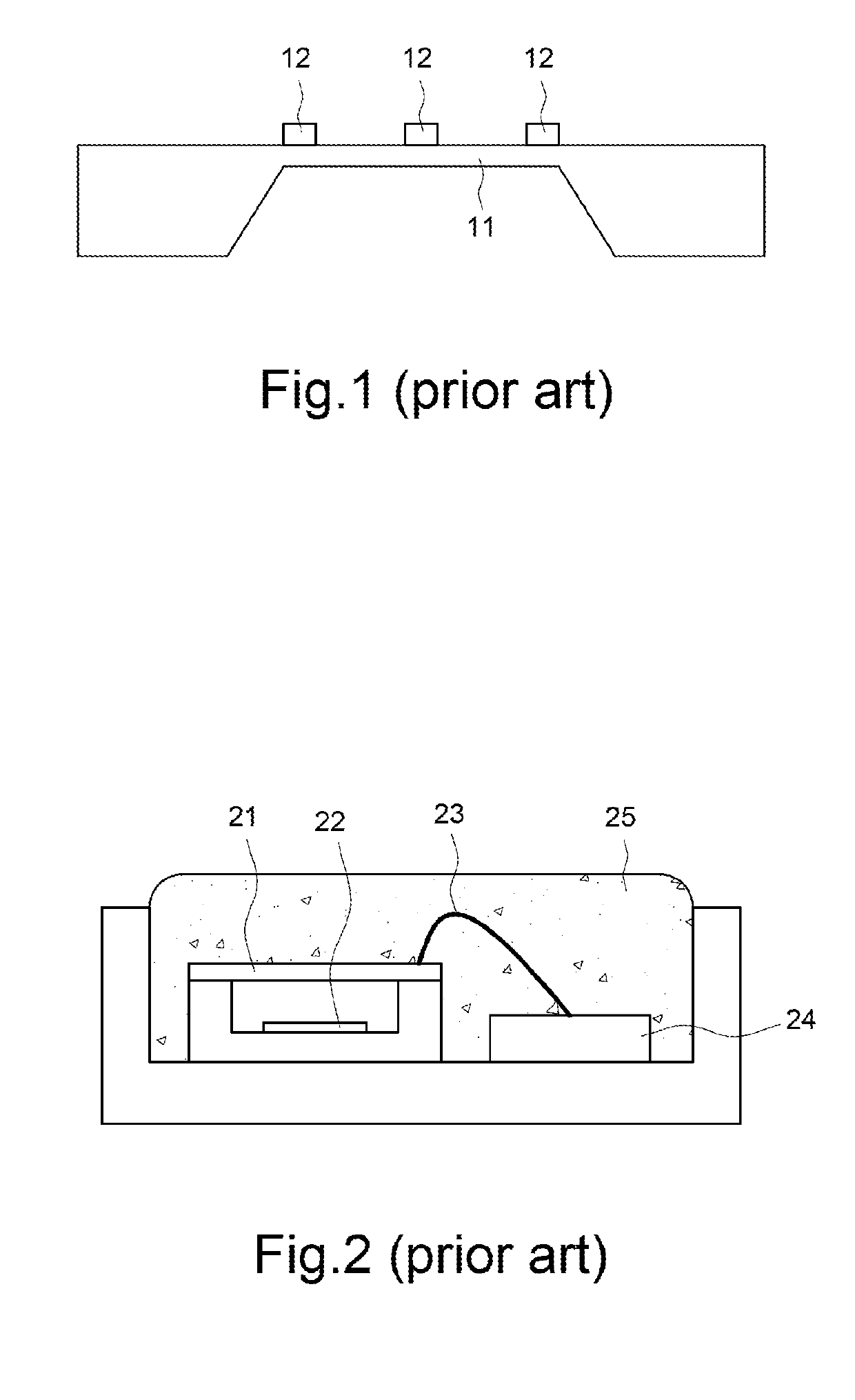
In view of the abovementioned structures, repeated pressing actions may degrade the reliability of the package body 25 and/or wire bonding structure, or even damage the mobile membrane.
Besides, the magnitude of the str

Method used


Image

  • Force sensor and manufacture method thereof
  • Force sensor and manufacture method thereof
  • Force sensor and manufacture method thereof

Examples


Embodiment Construction

[0023]The present invention will be described in detail with embodiments and attached drawings below. However, these embodiments are only to exemplify the present invention but not to limit the scope of the present invention. In addition to the embodiments described in the specification, the present invention also applies to other embodiments. Further, any modification, variation, or substitution, which can be easily made by the persons skilled in that art according to the embodiment of the present invention, is to be also included within the scope of the present invention, which is based on the claims stated below. Although many special details are provided herein to make the readers more fully understand the present invention, the present invention can still be practiced under a condition that these special details are partially or completely omitted. Besides, the elements or steps, which are well known by the persons skilled in the art, are not described herein lest the present i...


PUM

PropertyMeasurementUnit
Timeaaaaaaaaaa
Electrical conductoraaaaaaaaaa
Areaaaaaaaaaaa

Abstract

A force sensor comprises a first substrate, a second substrate, a third substrate, and a package body. The first substrate includes a fixed electrode, at least one first conductive contact, and at least one second conductive contact. The second substrate is disposed on the first substrate and electrically connected to the first conductive contact of the first substrate. The second substrate includes a micro-electro-mechanical system (MEMS) element corresponding to the fixed electrode. The third substrate is disposed on the second substrate and includes a pillar connected to the MEMS element. The package body covers the third substrate. The foregoing force sensor has better reliability.

Description

BACKGROUND OF THE INVENTION1. Field of the Invention[0001]The present invention relates to a force sensor and a manufacture method thereof, particularly to a MEMS-based force sensor and a manufacture method thereof.2. Description of the Prior Art[0002]Since the concept of the microelectromechanical system (MEMS) emerged in 1970s, MEMS devices have evolved from the targets explored in laboratories into the objects integrated with high-level systems. Nowadays, MEMS-based devices have been extensively used in consumer electronics, and the application thereof is still growing stably and fast. A MEMS-based device includes a mobile MEMS component. The function of a MEMS-based device may be realized through measuring the physical magnitude of the movement of the MEMS component. The force sensor is an example of MEMS devices, able to detect a pressing action or a pressing force.[0003]The conventional force sensors include the piezoresistor type pressure sensor and the capacitor type pressur...

Claims


Application Information

Patent Timeline
IPC IPC(8): B81B7/00B81C1/00G01L1/14
CPCB81B2203/04B81C2203/0785B81B2207/012B81B2201/0264B81B7/0051G01L1/148B81C1/0023B81B3/0072B81C1/00269B81C1/00666G01L1/14G01L9/12B81B7/0077B81B2201/0292B81B2203/0154B81B2203/0163B81B2203/053B81C2203/0792G01L1/142G01L1/144
Inventor TSENG, LI-TIENCHIEN, YU-HAOKUO, CHIH-LIANGYEH, YU-TE
Owner MIRAMEMS SENSING TECH
Why Eureka
Try Eureka