Digital active optical target detection system

Active Publication Date: 2019-10-31
RAYTHEON CO
View PDF2 Cites 0 Cited by
  • Summary
  • Abstract
  • Description
  • Claims
  • Application Information

AI Technical Summary

Benefits of technology

[0003]The present disclosure provides a detection system that overcomes one or more of these deficiencies of conventional sensor systems. The detection system is not dependent on formation of an image in a 2D plane by an array of a plurality of pixels or on the attainment of one or more thresholds, and thus is

Problems solved by technology

Conventional sensor systems, such as those for use on a projectile, often can distinguish between a target and other solid objects but encounter difficulty distinguishing between aerosols, such as those having particles spaced together in a volume, and a denser volume of a target.
Such system also can be frustrated by reflections, such as from a liquid or other reflective surface, when imaging targe

Method used


Image

  • Digital active optical target detection system
  • Digital active optical target detection system
  • Digital active optical target detection system

Examples


Example

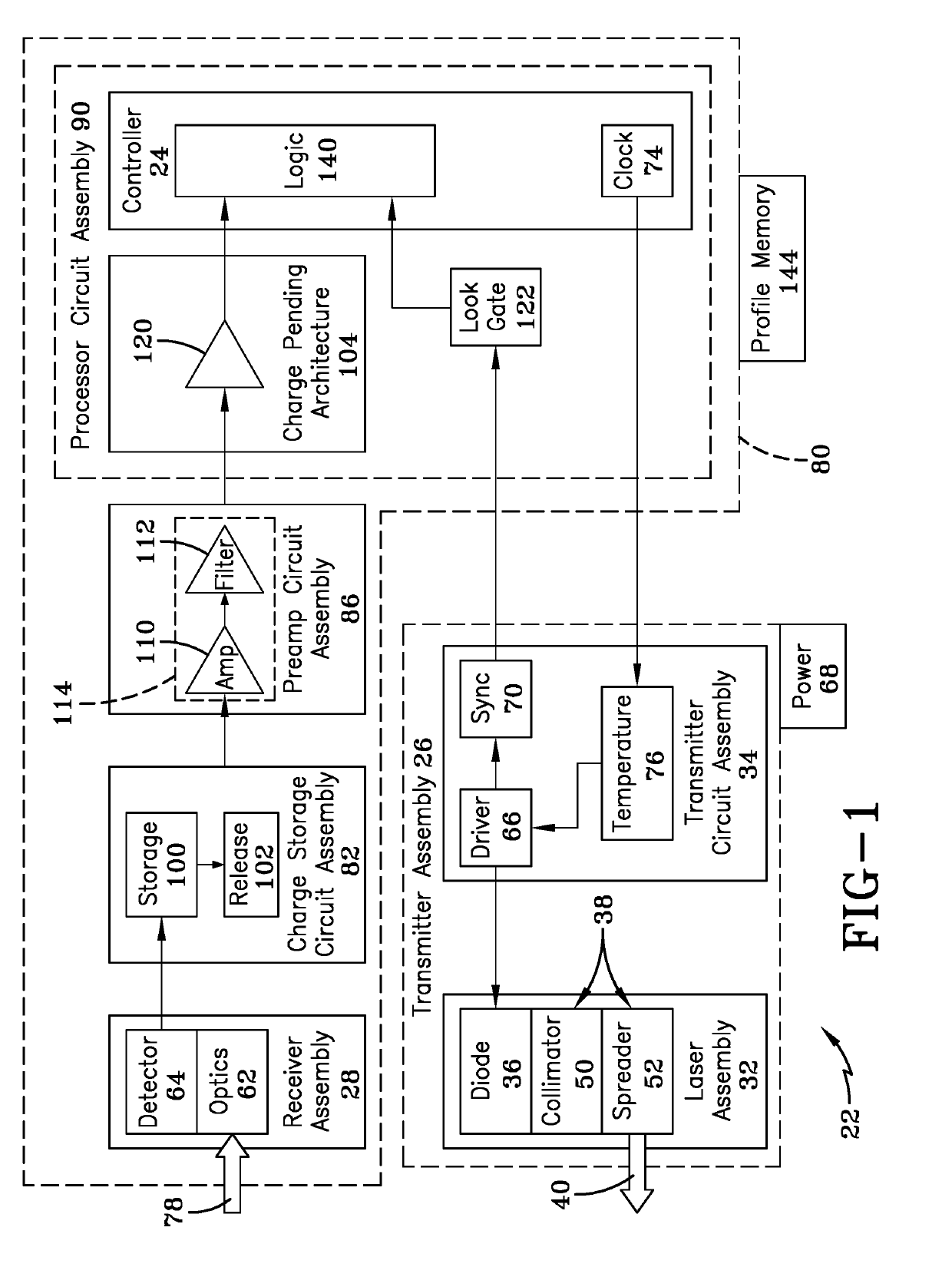
[0038]The present invention provides a detection system for analyzing an environment about the detection system, such as during movement of the detection system through the environment. Likewise, the detection system may be stationary and detect environmental elements moving past the detection system.

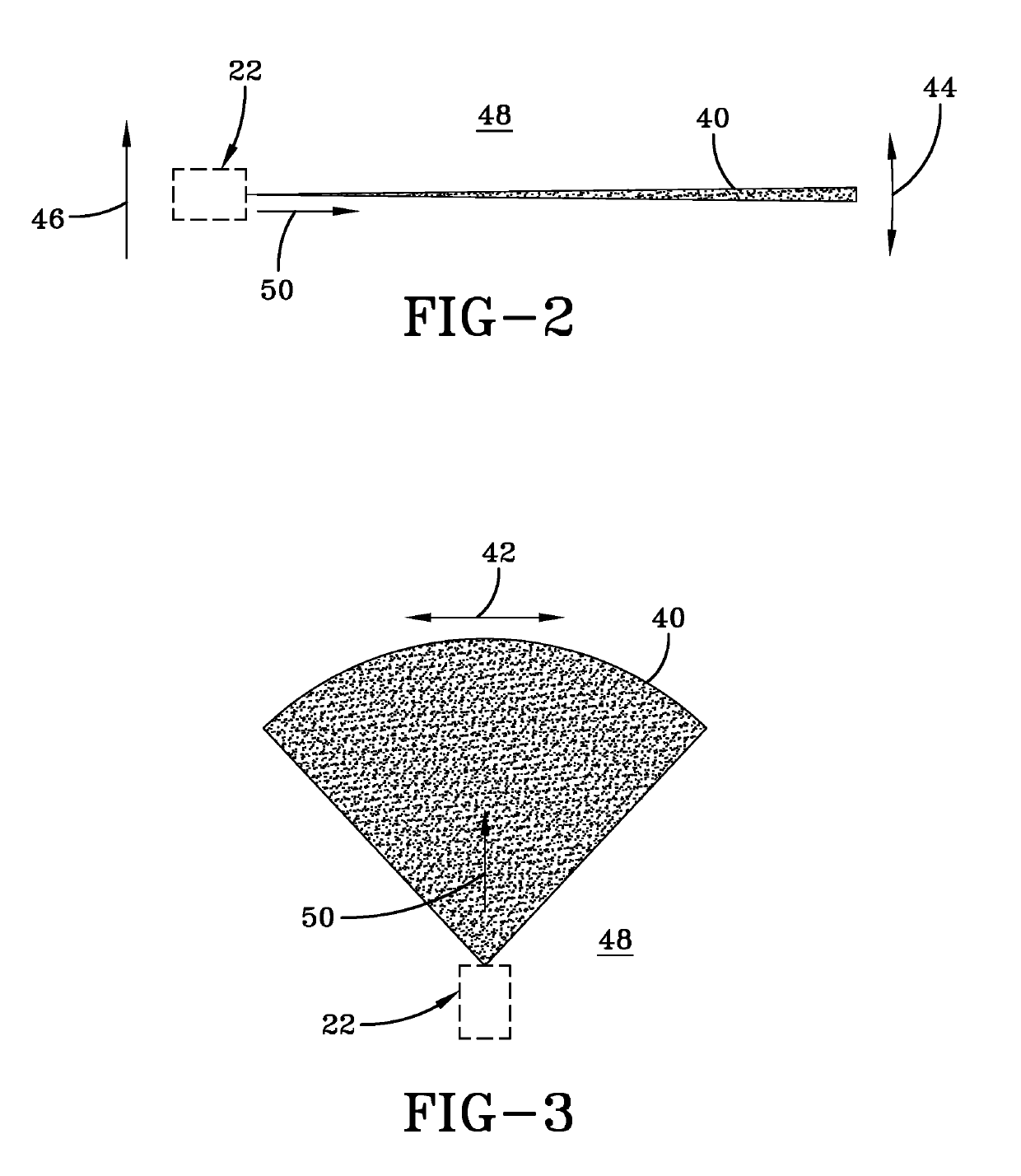
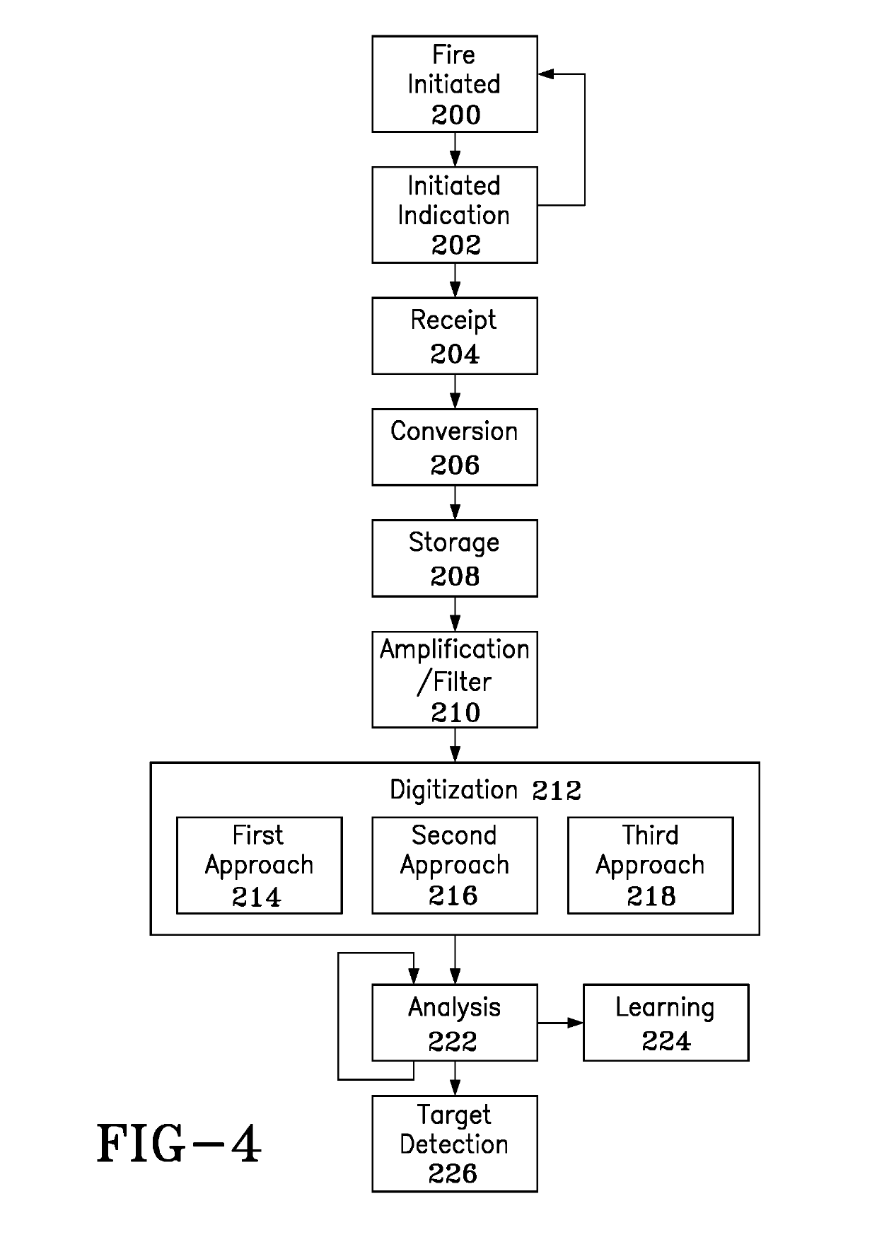
[0039]The detection system generally is configured to transmit and receive pulses of energy for the purpose of compiling a profile of environmental elements, such as those being passed by a detection system in transit. The profiles are functions of intensity of energy received versus a time element, such as a time of digitization along a respective flight path, for example. Pulse energy received may include multiplicities of pulse signatures, and a plurality of pulses per energy emission may be analyzed in concert for developing the aforesaid profile, the detection system being configured to compare the profiles against a library of known profiles to distinguish between environmental el...


PUM


Abstract

Provided is a detection system that utilizes high dynamic range, monolithically arranged, digital pixel sensors for situational awareness, targeting, tracking or locating. The detection system transmits a radially outwardly directed set of laser pulses into an environment, aspects of the pulses being reflected back by environmental elements to a single pixel array. The single pixel array scans volumetric space proximate the environment for profile characterization of the reflected aspects by the detection system in terms of intensity and multiplicity. The detection system is configured to compare this profile against a library of profiles of known environmental elements to distinguish between the environmental elements and a target. The detection system may be disposed about an outer periphery of a projectile for use in determining when the projectile is proximate the target for triggering an actionable element of the projectile, such as an initiator fuze for an explosive system.

Description

FIELD OF THE INVENTION[0001]The invention relates generally to a detection system for analyzing an environment about the detection system during movement of the detection system through the environment, and more particularly to a movable projectile having a target detection system for analyzing an environment about the projectile during its movement through the environment to determine proximity of the projectile to a target and thereby to activate an actionable element.DESCRIPTION OF THE RELATED ART[0002]When moving through a three-dimensional environment, a target detection system may encounter various interferrents, which may include aerosols and moving or non-moving objects. Conventional sensor systems, such as those for use on a projectile, often can distinguish between a target and other solid objects but encounter difficulty distinguishing between aerosols, such as those having particles spaced together in a volume, and a denser volume of a target. Such system also can be fru...

Claims


Application Information

Patent Timeline
IPC IPC(8): G01S17/02G01S7/481F42C13/02G01S7/4863G01S17/04G01S17/10G01S17/89
CPCG01S7/4811G01S17/026F42C13/023F42C13/02G01S7/4802G01S7/4863G01S7/487G01S17/10G01S17/89G01S17/04
Inventor CRAWFORD, JOHN OKERSON
Owner RAYTHEON CO
Why Eureka
Try Eureka