
Gearbox filler assembly

a gearbox and assembly technology, applied in the direction of lubricant transfer, machines/engines, transportation and packaging, etc., can solve the problems of affecting the performance of the rotorcraft, the failure of the entire drive system, so as to prevent the accumulation of large amounts of lubricant

Active Publication Date: 2019-11-07
TEXTRON INNOVATIONS
View PDF12 Cites 0 Cited by
  • Summary
  • Abstract
  • Description
  • Claims
  • Application Information

AI Technical Summary

Benefits of technology

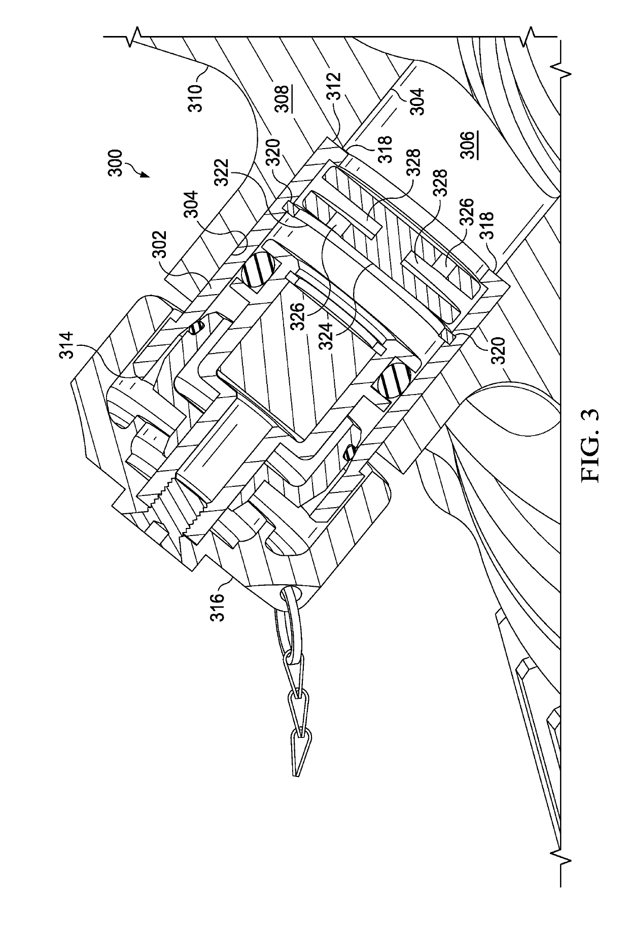
The present invention provides a method for managing lubricant in a gearbox. This method involves adding lubricant through a port in the gearbox without removing a baffle, which prevents large amounts of lubricant from splashing out of the gearbox. The baffle prevents debris from entering the gearbox while still allowing lubricant to flow through it. The baffle has multiple openings that allow lubricant to flow into the gearbox and prevent it from splashing out. The baffle also has a space between two disks, which allows lubricant to flow through it. The technical effects of this method are that it ensures proper lubrication of the gearbox without causing any damage to the environment and prevents excessive lubricant from being wasted.

Problems solved by technology

However, despite advances in materials and design, a number of failures continue to occur that affect rotorcraft performance.
One example of a problem with current rotorcraft drive systems is that, in some instances, the failure of single drive system component leads to failure of the entire drive system.
More particularly, the failure of a single gearbox or shaft connected to the main rotor gearbox can significantly impact operations.
For example, if there is a loss of lubrication to a gearbox, the gearbox loses torque transmission, causing damage to upstream or downstream components.
The same can occur when a shaft becomes unbalanced (or breaks), which can damage couplings, gearboxes and even the main rotor gearbox.
Unfortunately, when a portion of a drive system experiences a failure or reduction in performance, the concomitant reduction in power leads to challenges with flight performance.

Method used


Image

  • Gearbox filler assembly
  • Gearbox filler assembly
  • Gearbox filler assembly

Examples


Embodiment Construction

[0019]Illustrative embodiments of the system of the present application are described below. In the interest of clarity, not all features of an actual implementation are described in this specification. It will of course be appreciated that in the development of any such actual embodiment, numerous implementation-specific decisions must be made to achieve the developer's specific goals, such as compliance with system-related and business-related constraints, which will vary from one implementation to another. Moreover, it will be appreciated that such a development effort might be complex and time-consuming but would nevertheless be a routine undertaking for those of ordinary skill in the art having the benefit of this disclosure.

[0020]In the specification, reference may be made to the spatial relationships between various components and to the spatial orientation of various aspects of components as the devices are depicted in the attached drawings. However, as will be recognized by...


PUM


Abstract

A gearbox filler assembly includes a cylindrical insert attached to an interior of a port disposed within a housing of the gearbox. The cylindrical insert has a first end disposed within the port, a second end extending outward from the port and is configured to receive a detachable filler cap, a retaining lip around at least a portion of a first interior circumference proximate to the first end, and a retaining slot around at least a second interior circumference between the retaining lip and the second end. A retaining ring is detachably coupled within the retaining slot. A cylindrical baffle is detachably retained between the retaining ring and the retaining lip.

Description

CROSS-REFERENCE TO RELATED APPLICATIONS[0001]This patent application is related to U.S. provisional patent application Ser. No. 62 / 399,067 filed on Sep. 23, 2016 entitled “Improved Helicopter Transmission System” and U.S. provisional patent application Ser. No. 62 / 423,371 filed on Nov. 17, 2016 entitled “Improved Helicopter Transmission System,” all of which is hereby incorporated by reference in its entirety.STATEMENT OF FEDERALLY FUNDED RESEARCH[0002]Not applicable.TECHNICAL FIELD OF THE INVENTION[0003]The present invention relates in general to the field of lubricant filling ports, and more particularly, to a gearbox filler assembly for use in an aircraft, for example, a rotorcraft.BACKGROUND OF THE INVENTION[0004]Without limiting the scope of the invention, its background is described in connection with rotorcraft having gearbox filling ports.[0005]Since their inception, rotorcraft and rotorcraft drive systems have been improved to reduce the possibility of failure during flight...

Claims


Application Information

Patent Timeline
Patent Type & Authority Applications(United States)
IPC IPC(8): F16H57/04F16H57/01B64C27/12
CPCF16H2057/012F16H57/0408B64C27/12F16H57/01B64C27/14B64D35/04F01M11/0458F01M2011/0491F16N37/00F16N2210/08F16N2210/12
Inventor POSTER, SCOTT DAVID
Owner TEXTRON INNOVATIONS
Learn More