
Low density fluid displacement to generate power

a technology of low density and fluid displacement, applied in the direction of machines/engines, electrical storage systems, vessels, etc., can solve the problems of increasing the height of floating structures above the surface of liquids, clogging pipes, and reducing the efficiency of boats and other water vehicles, so as to reduce reduce the cost of equipment. , the effect of increasing the height of floating structures

Active Publication Date: 2019-11-14
INNOVATOR ENERGY LLC
View PDF6 Cites 0 Cited by
  • Summary
  • Abstract
  • Description
  • Claims
  • Application Information

AI Technical Summary

Benefits of technology

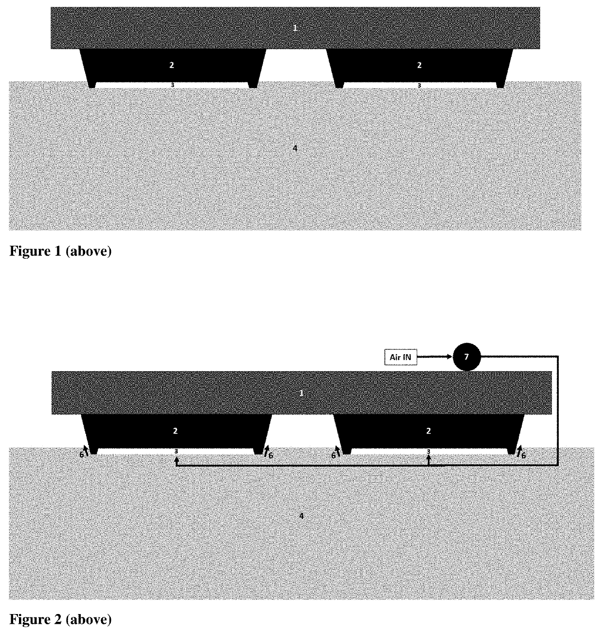
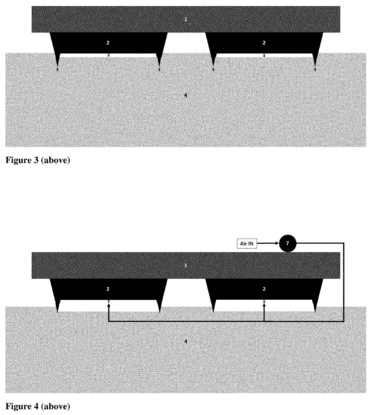
The patent text describes a way to increase or decrease the height of a floating structure, like a dock, by pumping air into or out of a cavity underneath it. This can be done using tubes and allows for the transfer of air without using moving parts that are in contact with water or the liquid. The technical effect is an improved and cost-effective way to adjust the height of a floating structure while minimizing the risk of fouling and increasing lifespan.

Problems solved by technology

Scaling, fouling, other ‘growths’, and corrosion can be damaging to water infrastructure and other liquid infrastructure.
Scaling, fouling, other ‘growths’, and corrosion can reduce infrastructure lifespan, infrastructure structural integrity, the efficiency of boats and other water vehicles through increased drag and weight, clog pipes, and reduce the buoyancy of docks and buoys.
They are generally bad for environment and may be toxic to aquatic ecosystems.
They are generally expensive, including due to material cost, application cost, and their temporary nature.
Barnacles and other growths can add significant weight to docks and can damage or puncture dock pontoons.
Removal is expensive, labor intensive, and only a temporary solution.

Method used


Image

  • Low density fluid displacement to generate power
  • Low density fluid displacement to generate power
  • Low density fluid displacement to generate power

Examples


example embodiment

Equipment and Description:

[0059]Example cost estimates for a dock module:[0060]Large Dock Module Dimensions: 8 meters long×5 meters wide×¾ meter tall.[0061]Contains concave region on bottom of dock which is about 5 meters long, 3 meters wide, and 0.07 meter deep (1.05 cubic meters total volume of concave region).[0062]The below cost estimates assume the dock either was built with a concave region or retrofitted with a concave region[0063]Example Equipment for Embodiment with Grid Electricity Source on Dock (Material CAPEX):[0064]Air pump—for example: 0.38 PSI, 200 Liters per minute, 35 watts, $12[0065]½ inch inside diameter vinyl tubing, 50 ft: $30[0066]Low power timer breakout: $13[0067]Triple-Axis Gyro Breakout Board (which may also trigger on / off switch when angle of dock changes): $12.50[0068]Total CAPEX: $67.50[0069]Example Embodiment with Grid Electricity Source on Dock (Annual OPEX with On-Off Timer):[0070]Assumes Pump Operates on a Timer of 2.5 minutes every 30 minutes or 5 ...

example exemplary embodiments

[0349]A tidal power system comprising:[0350]A region comprising a cavity, or concave region, or a storage region surrounded by at least a portion water impermeable material[0351]Wherein water displaces air from said region at relatively high tides,[0352]Wherein air displaces water at relatively lower tides[0353]Wherein electricity is generated from movement of air to or from said region

example exemplary sub-embodiments

[0354]Wherein energy or electricity is generated using a pneumatic turbine or generator[0355]Wherein said region is located beneath the surface of the ground, or inside a causeway, or a landfill, or an artificial island, or a breakwall, or a building foundation, or a structure foundation, or a combination thereof[0356]Wherein said storage region contains a porous fill material[0357]Wherein said porous fill material comprises one or more or a combination of the following: sand, gravel, rock, packing material, or cinderblock, or plastic bottles, or plastic containers, or plastic buckets, or interconnected cinderblock, or interconnected plastic containers, or interconnected packing material[0358]Wherein said water impermeable material may comprise a liner[0359]Wherein air exits and enters said region using a pipe[0360]Wherein said pipe has an opening inside said storage region or an opening above the surface of the water or both[0361]Wherein water enters or exits said region via water ...


PUM


Abstract

The present invention relates to systems and methods for pumping or removing a fluid from a region within or on top of or in contact with a water or liquid body and applications for said systems and methods. Some embodiments may be applicable to, for example, inhibiting or preventing growth formation or fouling of structures in liquid environments. Other embodiments may be applicable to, for example, an energy storage device or a tidal power energy generation system.

Description

CROSS REFERENCE TO RELATED APPLICATIONS[0001]The instant application claims priority to provisional application No. 62 / 670,133 filed May 11, 2018 which is hereby incorporated by reference in its entirety.BACKGROUND OF INVENTION[0002]Scaling, fouling, other ‘growths’, and corrosion can be damaging to water infrastructure and other liquid infrastructure. Scaling, fouling, other ‘growths’, and corrosion can reduce infrastructure lifespan, infrastructure structural integrity, the efficiency of boats and other water vehicles through increased drag and weight, clog pipes, and reduce the buoyancy of docks and buoys.[0003]Prior art technologies for preventing scaling, fouling, and other ‘growths’ include anti-foulants and antiscalants. Anti-foulants and antiscalants have multiple significant disadvantages. They are generally bad for environment and may be toxic to aquatic ecosystems. They are generally only temporary and require re-application or replacement for continued effectiveness. The...

Claims


Application Information

Patent Timeline
IPC IPC(8): F03B13/06F03G3/00
CPCF03B13/06H02J15/003F03G3/00H02J15/006F03B13/266F05B2260/42E02B9/08B63B59/04B63B2035/4466Y02E60/16Y02E10/30B60V1/046B60V3/065F03B13/264F03B13/268
Inventor NOVEK, ETHAN J.
Owner INNOVATOR ENERGY LLC
Learn More