Piezoelectric ring gyroscope

a ring gyroscope and piezoelectric technology, applied in the direction of speed measurement using gyroscopic effects, instruments, surveying and navigation, etc., can solve the problems of small capacitors, limited extension of secondary mode detection electrodes, and small electrostatic force generated by capacitors

Active Publication Date: 2019-11-14
MURATA MFG CO LTD
View PDF0 Cites 14 Cited by
  • Summary
  • Abstract
  • Description
  • Claims
  • Application Information

AI Technical Summary

Benefits of technology

[0016]An object of the present disclosure is to provide an apparatus which alleviates the above disadvantages.

Problems solved by technology

In these gyroscopes the detection capacitances are very small since it is very difficult to manufacture air gaps smaller than 1 μm, and the high amplitude of the primary oscillation puts limits on how far from the nodal points the secondary mode detection electrodes can be extended.
On the other hand, the excitation capacitors needed for the primary mode must have a large gap to allow large amplitude oscillation, and thus the electrostatic force generated by these capacitors remains very small.
Such devices are typically not compatible with the standard packaging requirements of silicon devices.

Method used


Image

  • Piezoelectric ring gyroscope
  • Piezoelectric ring gyroscope
  • Piezoelectric ring gyroscope

Examples


Embodiment Construction

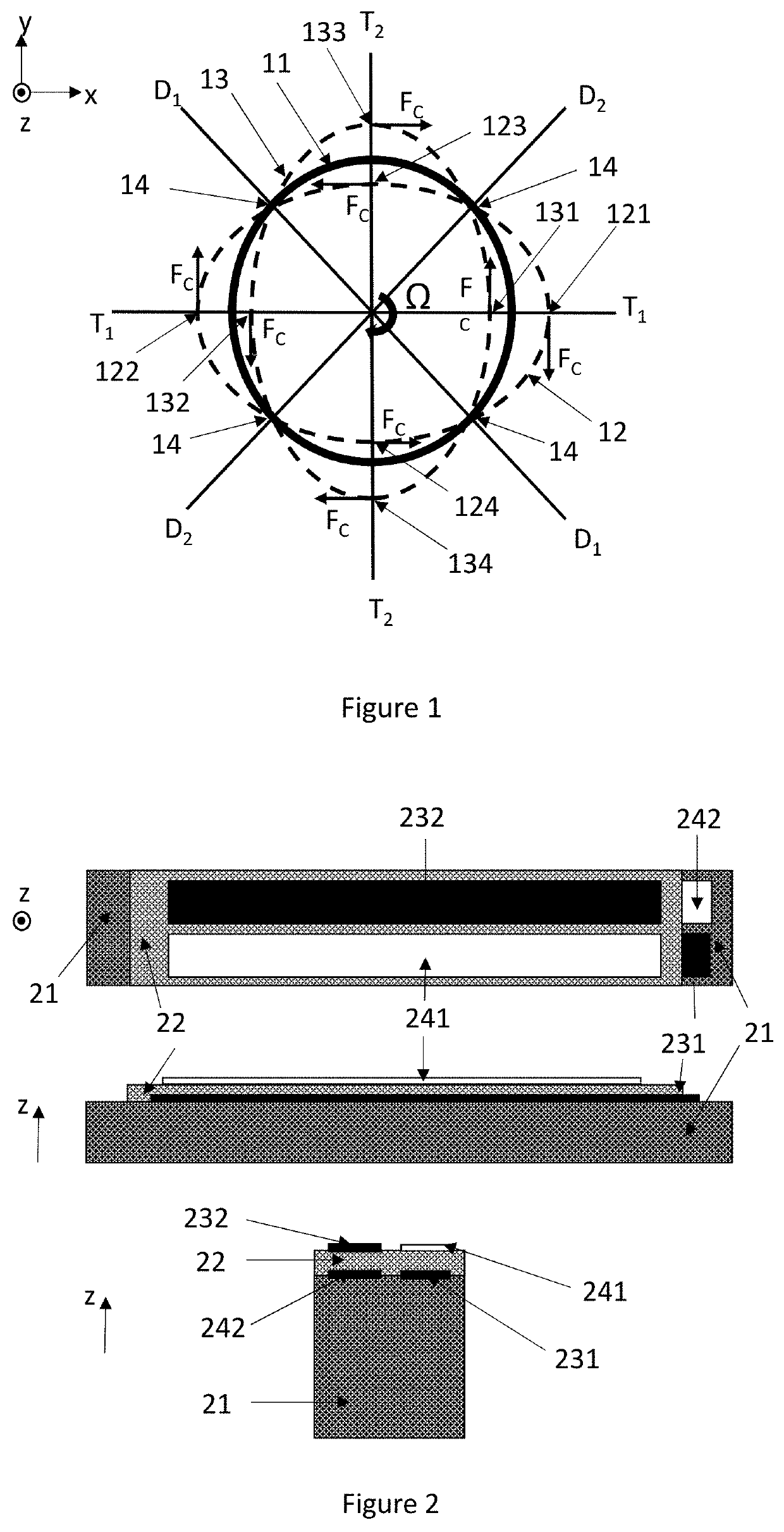
[0037]FIG. 2 illustrates three cross-sections of a bending piezoelectric transducer placed on a gyroscope ring. The transducer can generate or measure bending motion in the xy-plane. A pair of first electrode layers 241 and 242 have been placed on silicon ring 21, one on the upper side of a layer of piezoelectric material 22 and one on the lower side (up and down refers in this case to the direction of the z-axis). These electrodes are paired with second electrode layers 231 and 232, respectively, as illustrated in the figure. Layers 241, 22 and 231 together form a first piezoelectric transducer on top of the ring 21, and layers 242, 22 and 232 together form a second piezoelectric transducer on top of the ring 21.

[0038]If drive voltages with opposite polarity are applied to these two transducers, the two transducers produce opposite strains in the xy-plane, which can deform silicon ring 21. If the transducers are used as sense transducers, in-plane bending will generate a voltage di...


PUM


Abstract

A ring gyroscope which comprises a substantially circular and flexible ring which defines a ring plane, one or more primary piezoelectric split transducers configured to drive the ring into resonance oscillation, four or more mass elements which form a symmetrical mass distribution in relation to both a first and a second transversal symmetry axis and to a first and a second diagonal symmetry axis. The ring gyroscope also comprises a suspension structure configured to support the weight of the ring and the mass elements, wherein the suspension structure comprises N outer suspenders, where N is an integer greater than or equal to two, and each outer suspender extends along a ring tangent from a suspension attachment point on the outer edge of the ring to an anchor point.

Description

FIELD OF THE DISCLOSURE[0001]The present disclosure relates to sensors for measuring angular rotation rates, and more particularly to z-axis gyroscopes where the oscillation of a ring-shaped structure in a given plane is utilized to detect the magnitude of angular rotation about an axis perpendicular to that plane. The present disclosure further concerns transducers which may be used to drive the primary ring oscillation, to measure the magnitude of the primary ring oscillation, to detect the secondary ring oscillation induced by angular rotation, or to drive counter-oscillation in the secondary mode. The present disclosure also concerns means for adjusting the resonance properties of the ring with attached mass elements, and means for suspending the ring from a fixed substrate.BACKGROUND OF THE DISCLOSURE[0002]Microelectromechanical gyroscopes use the Coriolis effect to measure angular velocity. In vibrating MEMS gyroscopes, an object is driven into oscillating movement by an actua...

Claims


Application Information

Patent Timeline
Patent Type & Authority Applications(United States)
IPC IPC(8): G01C19/5712
CPCG01C19/5712G01C19/5684H03H9/02259H03H9/2431H03H2009/02346
Inventor KUISMA, HEIKKI
Owner MURATA MFG CO LTD
Why Eureka
Try Eureka