Maximum doppler extension via recursive chirp decimation

a technology of chirp decimation and maximum doppler, which is applied in the direction of reradiation, measurement devices, instruments, etc., can solve the problem that the velocity of some objects in the environment can exceed the maximum velocity

Active Publication Date: 2019-11-14
GM GLOBAL TECH OPERATIONS LLC
View PDF1 Cites 1 Cited by
  • Summary
  • Abstract
  • Description
  • Claims
  • Application Information

AI Technical Summary

Benefits of technology

[0008]In addition to one or more of the features described herein, the processor is further configured to partition the reflection into the plurality of streams in response to an external input. The processor is further configured to obtain a frequency space for each of the plurality of streams, determine a range of the object from at least one of the frequency spaces, combine the frequency spaces into a combined frequency space, and determine a Doppler frequency from the combined frequency space. The processor is further configured to correct a phase difference between the plurality of streams when combining the frequency spaces. The processor is further configured to determine a parameter of the object from the range of the object and the Doppler frequency and navigate the vehicle with respect to the object based on the parameter. The processor is further configured to determine the Doppler frequency from the combined frequency space by determining a frequency having a maximal intensity.

Problems solved by technology

However, in high velocity scenarios, such as on highways, the velocities of some objects in the environment can exceed the maximum velocity.

Method used


Image

  • Maximum doppler extension via recursive chirp decimation
  • Maximum doppler extension via recursive chirp decimation
  • Maximum doppler extension via recursive chirp decimation

Examples


Embodiment Construction

[0017]The following description is merely exemplary in nature and is not intended to limit the present disclosure, its application or uses. It should be understood that throughout the drawings, corresponding reference numerals indicate like or corresponding parts and features.

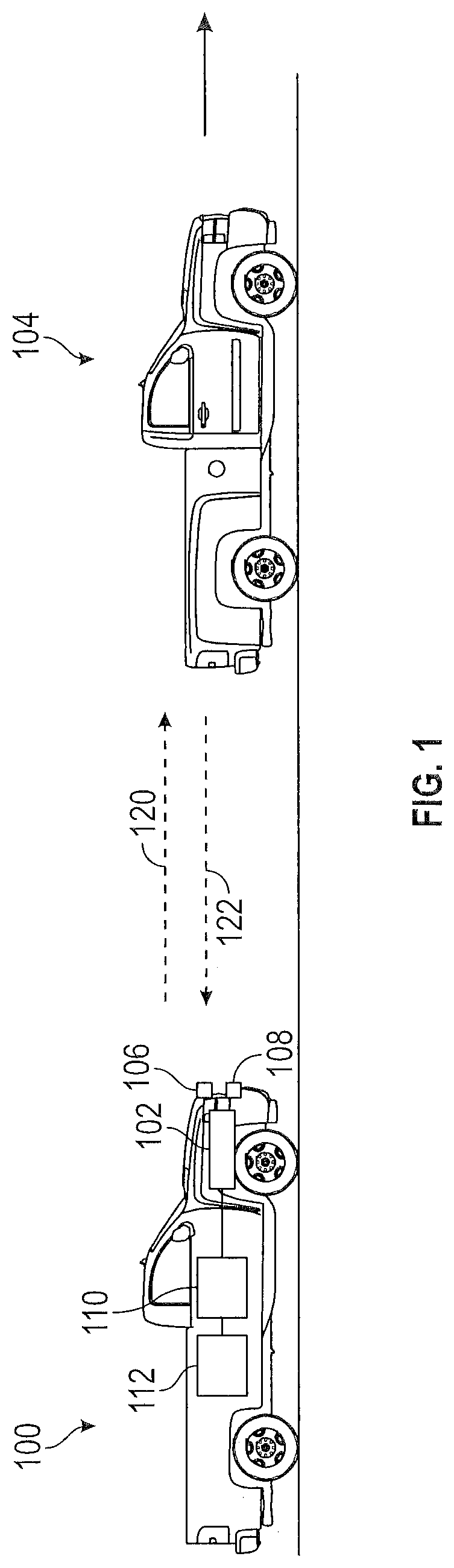
[0018]In accordance with an exemplary embodiment of the invention, FIG. 1 shows a vehicle 100, such as an automobile, that includes a radar system 102 suitable for determining relative velocity of a target or object 104 with respect to the vehicle 100. In the embodiment shown in FIG. 1, the radar system 102 includes a transmitter 106 and a receiver 108. In alternate embodiments, the radar system 102 may be a MIMO (multi-input, multi-output) radar system that includes an array of transmitters and an array of receivers. The radar system 102 controls and operates the transmitter 106 to generate a radio frequency wave (a “source signal”120). In one embodiment, the source signal 120 includes a linear frequency-modul...


PUM


Abstract

A vehicle, system for navigating the vehicle and method of operating the vehicle. The system includes a radar system and a processor. The radar system transmits a linear frequency modulated signal into an environment of the vehicle and receives a reflection of the linear frequency modulated signal from an object in the environment. The processor partitions the reflection into a plurality of streams to obtain a Doppler frequency that exceeds a maximum Doppler frequency of the radar.

Description

INTRODUCTION[0001]The subject disclosure relates to operation of radar systems and, in particular, to a method of extending a Doppler range of radar systems for high velocity objects.[0002]Many vehicles include radar systems for determining parameters of an object in an environment of the vehicle, such as a range and velocity of the object with respect to the vehicle. Determining these parameters allows the driver, or an autonomous driving system of the vehicle, to take an action in order to avoid contact with the object. The radar systems generally operate by transmitting a sequence of linear frequency modulated signals, each signal being followed by a measurement phase during which a reflection of the signal is received at a receiver. A maximum velocity that can be determined by the radar system is limited by the duration of a pulse repetition interval, which is the combined duration of the linear frequency modulated signal and of the measurement phase. In low velocity scenarios, ...

Claims


Application Information

Patent Timeline
Patent Type & Authority Applications(United States)
IPC IPC(8): G01S13/58G01S7/35G01S13/931
CPCG01S13/584G01S13/931G01S2007/356G01S7/352G01S13/32G01S7/356
Inventor VILLEVAL, SHAHARLONGMAN, ORENBILIK, IGAL
Owner GM GLOBAL TECH OPERATIONS LLC
Why Eureka
Try Eureka