Image display apparatus

Inactive Publication Date: 2019-11-14
RICOH KK
View PDF3 Cites 1 Cited by
  • Summary
  • Abstract
  • Description
  • Claims
  • Application Information

AI Technical Summary

Benefits of technology

The patent describes a way to hold a scanning member in place while it is being laser-scanned. This member can be curved with a specific shape in mind. The technical effect of this is that it allows for more precise and accurate scanning of images.

Problems solved by technology

When a flat screen is used in an HuD, variation undesirably arises in the length of optical path of light exiting from the flat screen and incident on a concave mirror.

Method used


Image

  • Image display apparatus
  • Image display apparatus
  • Image display apparatus

Examples


Embodiment Construction

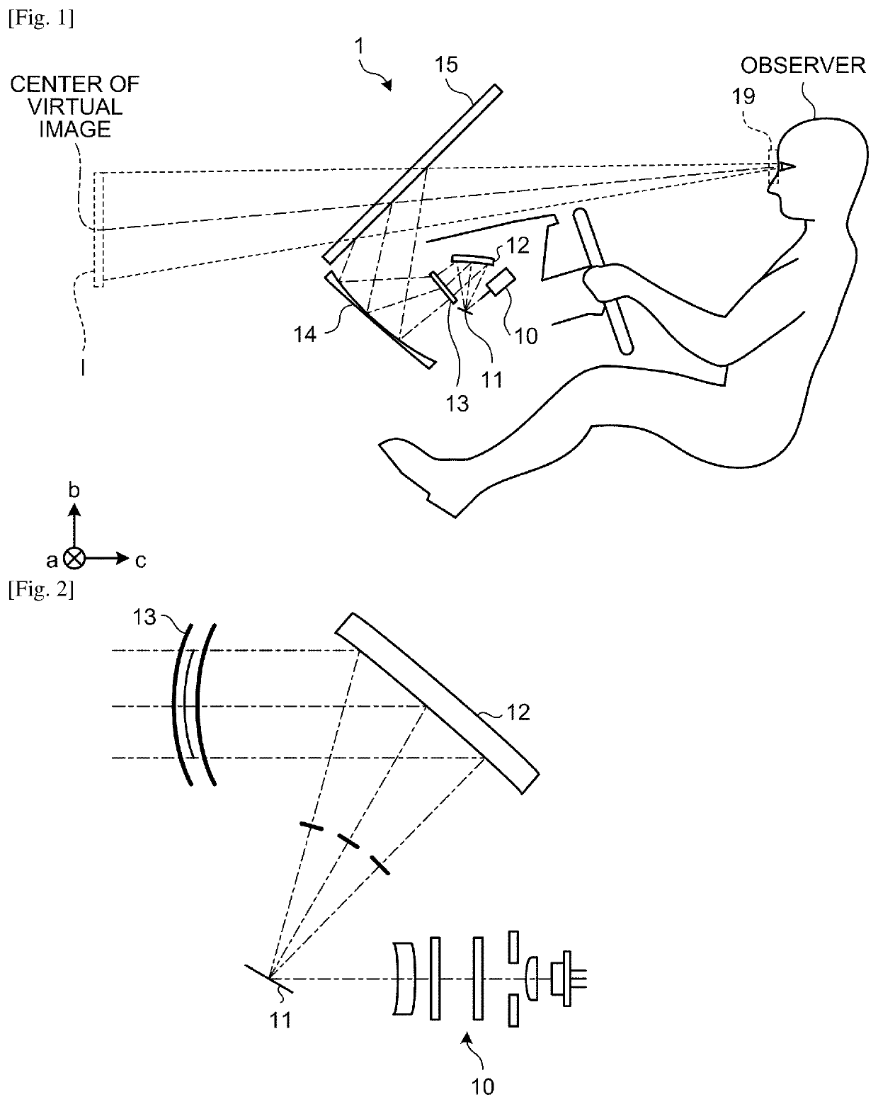
[0024]Embodiments of an image display apparatus are described below with reference to the accompanying drawings. FIG. 1 is a diagram illustrating an overview of an image display apparatus 1 according to an embodiment. The image display apparatus 1, which may be a head-up display (HuD) for example, is mounted on a mobile entity, such as a vehicle, aircraft, or ship.

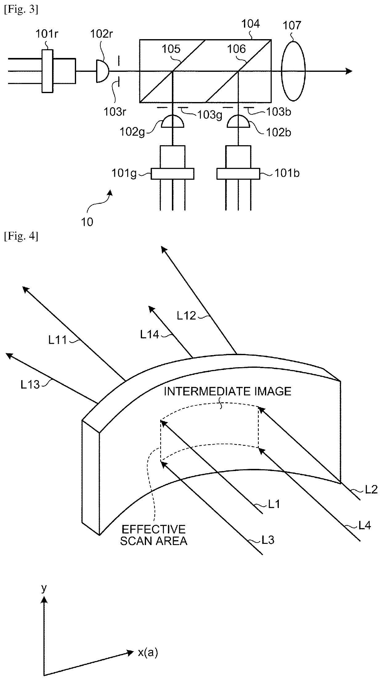
[0025]The image display apparatus 1 includes a light source unit (laser light source) 10, an optical deflector 11, a scanning mirror 12, a screen (to-be-scanned member) 13, a concave mirror 14, and a transparent reflective member 15. The transparent reflective member 15, which may be a front windshield of a vehicle for example, is irradiated with light, thereby enabling an observer to view a virtual image from the observer's eye point. The image display apparatus 1 makes navigation information (e.g., information about a velocity and traveled distance) necessary for driving a vehicle, visible via a front windshield (the tra...


PUM


Abstract

An image display apparatus includes: a laser light source configured to emit laser light in accordance with an image; an optical deflector configured to deflect the laser light emitted by the laser light source; a to-be-scanned member configured to make an image diverge at a predetermined angle of divergence, the image being drawn with the laser light deflected by the optical deflector; and a housing forming a curved housing space for housing the to-be-scanned member. The housing houses the to-be-scanned member in the housing space to let the to-be-scanned member curve with a predetermined curvature.

Description

TECHNICAL FIELD[0001]The present invention relates to an image display apparatus.BACKGROUND ART[0002]A vehicle head-up display (HuD) is known as an application that allows a driver of a vehicle to recognize an alarm or information with small movement of line of sight. Examples of the HuD includes a HuD of “panel type” that draws an intermediate image using an imaging device, such as a liquid crystal device or a digital micromirror device (DMD), and a HuD of “laser scan type” that scans a laser beam emitted by a laser diode using a two-dimensional scanning device to form an intermediate image.[0003]From a manufacturing issue, a microlens array or the like, on which a two-dimensional image (intermediate image) is to be drawn, of an HuD has conventionally been manufactured into a flat screen shape. When a flat screen is used in an HuD, variation undesirably arises in the length of optical path of light exiting from the flat screen and incident on a concave mirror. As a result, field cu...

Claims


Application Information

Patent Timeline
IPC IPC(8): G02B27/01H04N9/31G02B27/00
CPCG02B27/0101G02B2027/011G02B2027/013G02B27/0031H04N9/3129G02B27/0149G02B2027/0145
Inventor YOSHIMURA, KENICHIKUSUNOSE, NOBORU
Owner RICOH KK
Why Eureka
Try Eureka