
Boat hull

a technology for boats and hulls, applied in waterborne vessels, vessel parts, marine propulsion, etc., can solve problems such as increasing wave-making resistance, stalling the forward motion of the vessel, and constant challenges

Inactive Publication Date: 2019-11-21
LITTLE ANTHONY
View PDF0 Cites 0 Cited by
  • Summary
  • Abstract
  • Description
  • Claims
  • Application Information

AI Technical Summary

Benefits of technology

The invention provides a boat hull with a flat aft section that allows air to be introduced under the hull to lubricate its surface. The hull also includes at least one slot or hole that provides a low-pressure injection point for air or exhaust gas. The hull may also have secondary apertures, chines, or other features to improve its performance. The boat hull can be used in a boat with an internal propulsion system. The technical effects of the invention include improved lubrication of the flat aft section, improved air film formation, and improved performance of the boat hull.

Problems solved by technology

Designers constantly face challenges related to the ‘V’ hull form where each design attribute presents inherent compromises between that attribute and one or more others.
The compromise with this form is that when the bow buries into a large swell, the hull presents a relatively blunt form to the swell which increases wave-making resistance and partially stalls the vessel's forward motion.
The compromise with a flat underbody is that the vessel is only suited to flat water operation due to poor performance and excessive slamming loads in rough water.
These wave-making forces constitute large energy losses.
Consequently, the inclined bow buries the stern, creating a void in the water immediately aft of the hull as a result of water being displaced by the vessels motion.
This void is evidence of large energy losses.
The incline also increases the propulsion thrust line angle from the horizontal, which reduces the efficiency of the vessel as a whole.
Inclined planing vessels also present a relatively broad slamming area to the face of oncoming swells further reducing efficiency, reducing comfort and introducing unnecessary slamming loads and stresses to the vessel.
Displacement hulls by design cannot operate as a planing vessel.
However, a planing hull will operate in displacement mode at low speed which is a compromise of the design intent as it operates with a buried stern resulting in increased eddy-making resistance and reduced efficiency.
Displacing or relocating water consumes energy, therefore the lower the volume of displaced water and the shorter the displacement distance, the lower the energy required.
To this end, attempts have been made to introduce air bubbles and air films between the hull and the surface of the water with limited practical success.

Method used


Image

  • Boat hull
  • Boat hull
  • Boat hull

Examples


Embodiment Construction

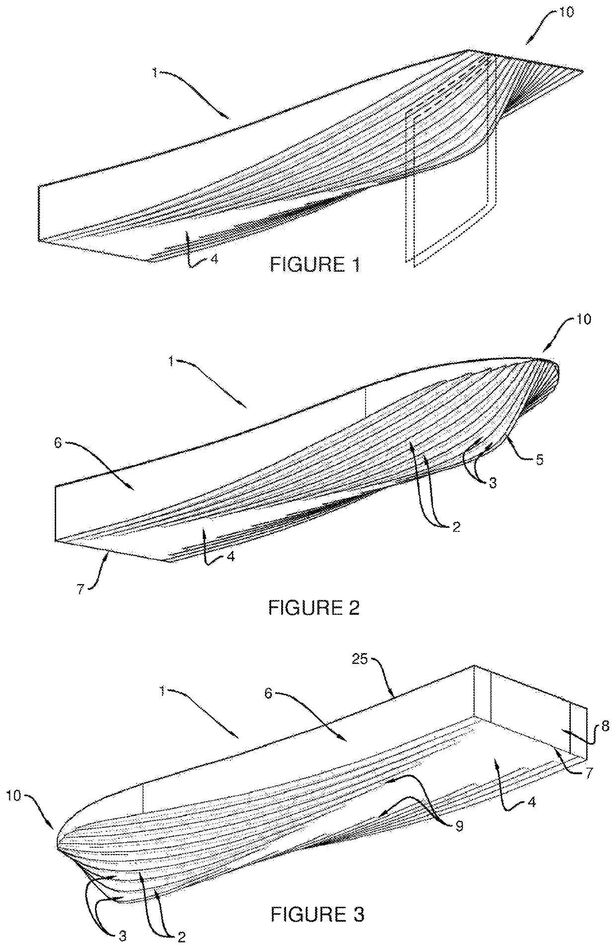
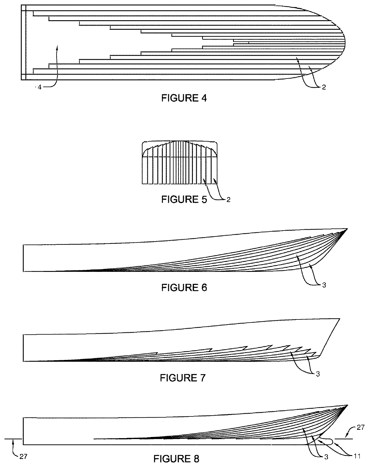
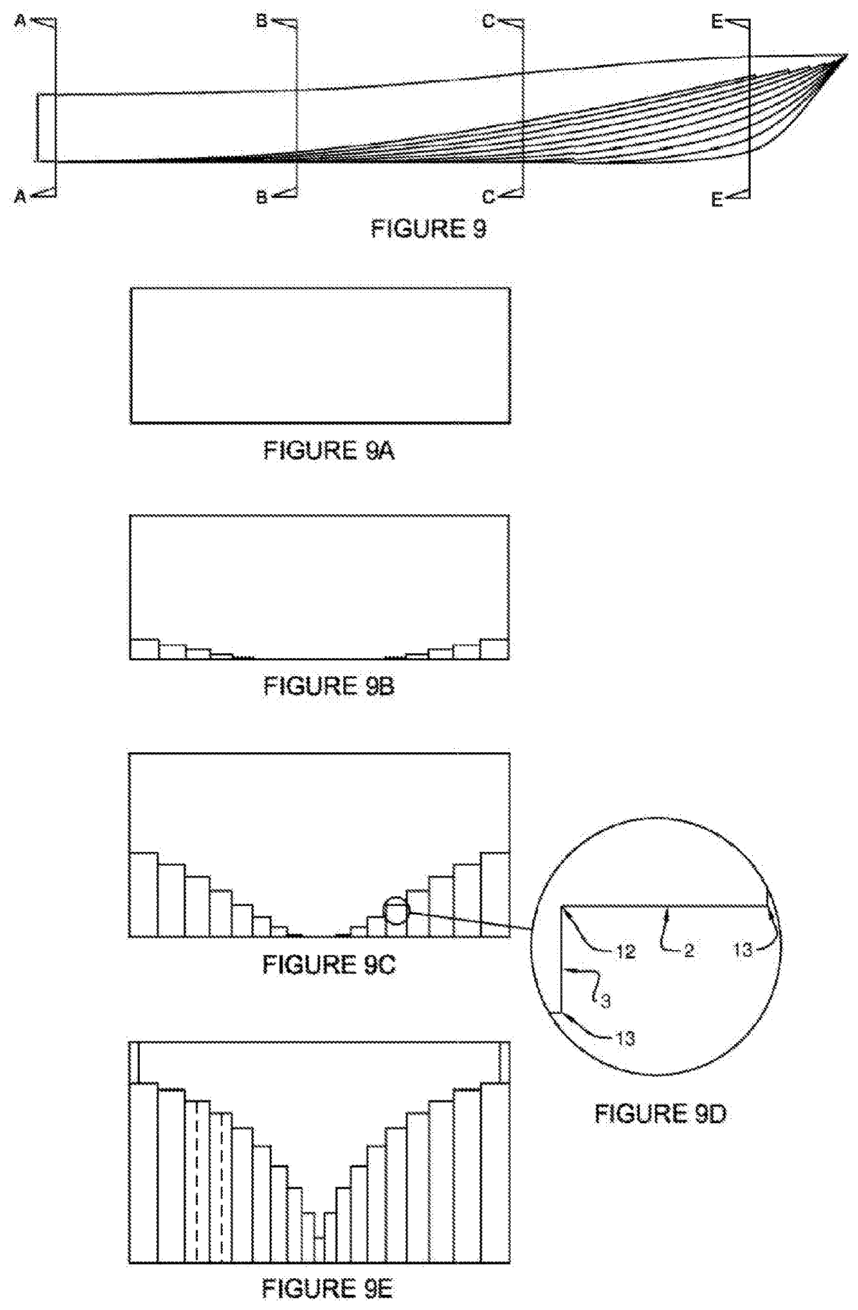
[0072]With reference to FIG. 1, there is shown a boat hull 1 according to a preferred embodiment of the invention. The boat hull 1 comprises a plurality of chines 2 extending downwardly from a bow 10 of the hull 1 towards a stern 7 or a base 4 of the hull 1. Each chine 2 is, in transverse cross section, substantially straight and substantially horizontal, as can be seen in FIG. 9D. Each chine 2 is also arranged so that a centreline or a line along the centre of the outer surface of the chine 2 lies in a plane which is parallel to a central plane of an adjacent chine 2, i.e. the adjacent chine is also configured so that a centreline of the chine lies in a plane, as indicated by the exemplary dashed line planes in FIG. 1 and exemplary dashed centrelines in FIG. 9E. Accordingly, although the chines 2 are inclined and offset from each other, in an underneath view, as illustrated in FIG. 4, the chines 2 appear parallel.

[0073]As can be seen in FIG. 9D, a substantially vertical surface 3 i...


PUM


Abstract

A boat hull includes a bow section and a flat aft section to allow an air film to be introduced under the boat hull. At least one slot or round hole is arranged proximate a location where the bow section meets the flat aft section. The slot or round hole provides a low-pressure injection point for pumped or drawn-in air and / or exhaust gas, which lubricates an operative surface of the flat aft section.

Description

CROSS-REFERENCE TO RELATED APPLICATIONS[0001]This application is a continuation-in-part of U.S. patent application Ser. No. 15 / 579,163, entitled BOAT HULL and filed Dec. 1, 2017, which is the national phase of International Application Serial No. PCT / AU2015 / 050308, entitled BOAT HULL and filed Jun. 4, 2015, the disclosure of which is hereby incorporated by reference in its entirety for all purposes.FIELD OF THE INVENTION[0002]The present invention relates to a boat hull. More generally, the present invention relates to improvements to the hydrodynamic efficiency of boat hulls, floats, sponsons or similar, designed to operate in light and / or heavy weather conditions. In addition, the invention relates to, among other things, improvements in seaworthiness, structural integrity and buildability of the aforementioned, referred to hereafter as a ‘boat hull’ or ‘hull’.BACKGROUND OF THE INVENTION[0003]Traditional boat hull design has evolved over many years with each new design being a dev...

Claims


Application Information

Patent Timeline
Patent Type & Authority Applications(United States)
IPC IPC(8): B63B1/06
CPCB63B1/063B63B1/22B63B2001/201B63B2001/206B63B2001/385B63B2001/387B63H11/00Y02T70/10
Inventor LITTLE, ANTHONY
Owner LITTLE ANTHONY
Features
  • Generate Ideas
  • Intellectual Property
  • Life Sciences
  • Materials
  • Tech Scout
  • Unparalleled Data Quality
  • Higher Quality Content
  • 60% Fewer Hallucinations
Learn More