
System and method of unspooling a material into a textile machine

a technology of unspooling mechanism and textile machine, which is applied in the direction of textiles and papermaking, thin material processing, knitting, etc., can solve the problems of material slipping, material overspin, and snag on the flange, etc., and achieve the effect of variable deployment speed

Pending Publication Date: 2019-11-21
FABDESIGNS
View PDF7 Cites 1 Cited by
  • Summary
  • Abstract
  • Description
  • Claims
  • Application Information

AI Technical Summary

Benefits of technology

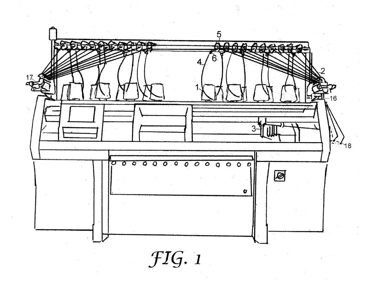
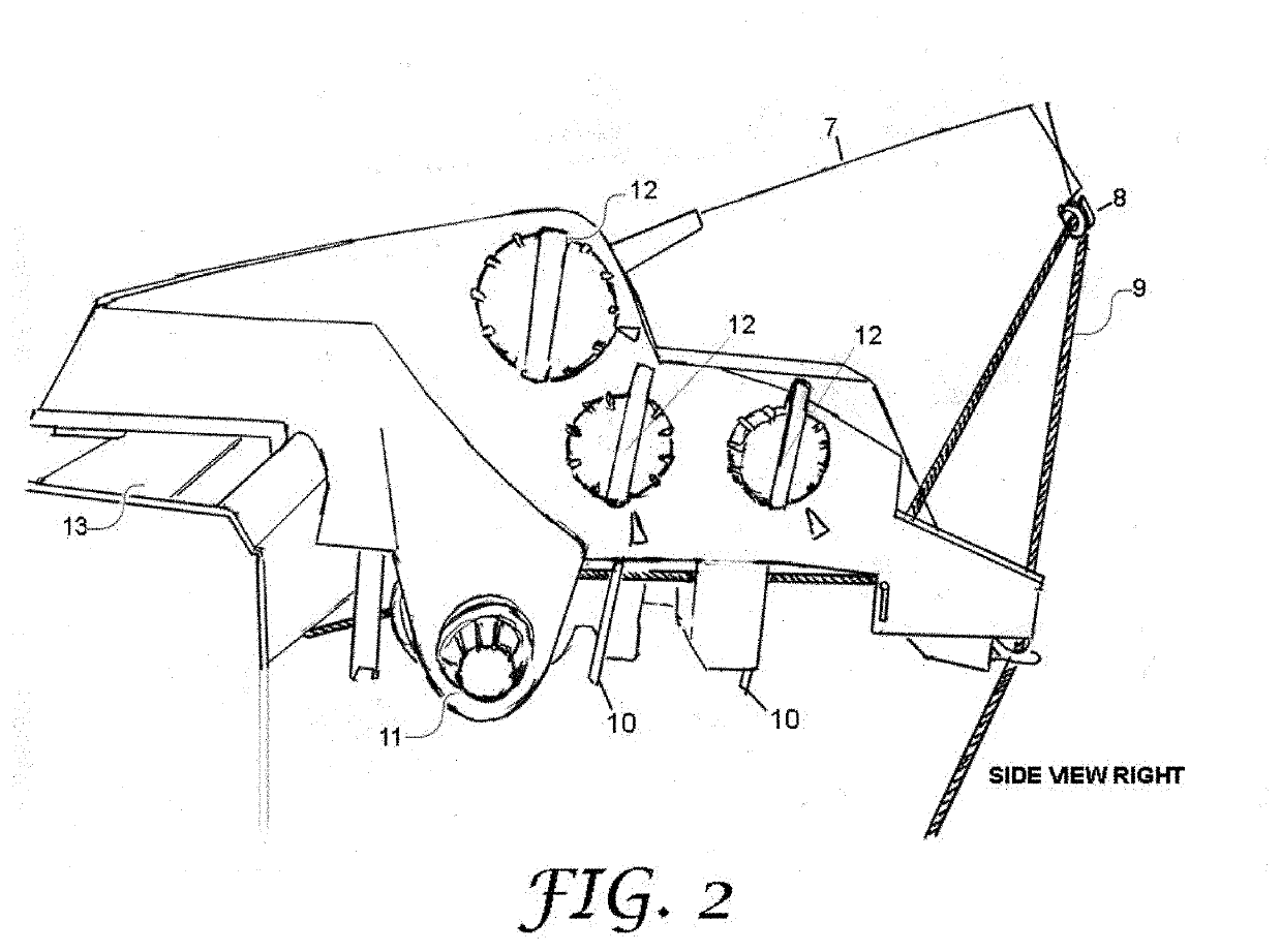
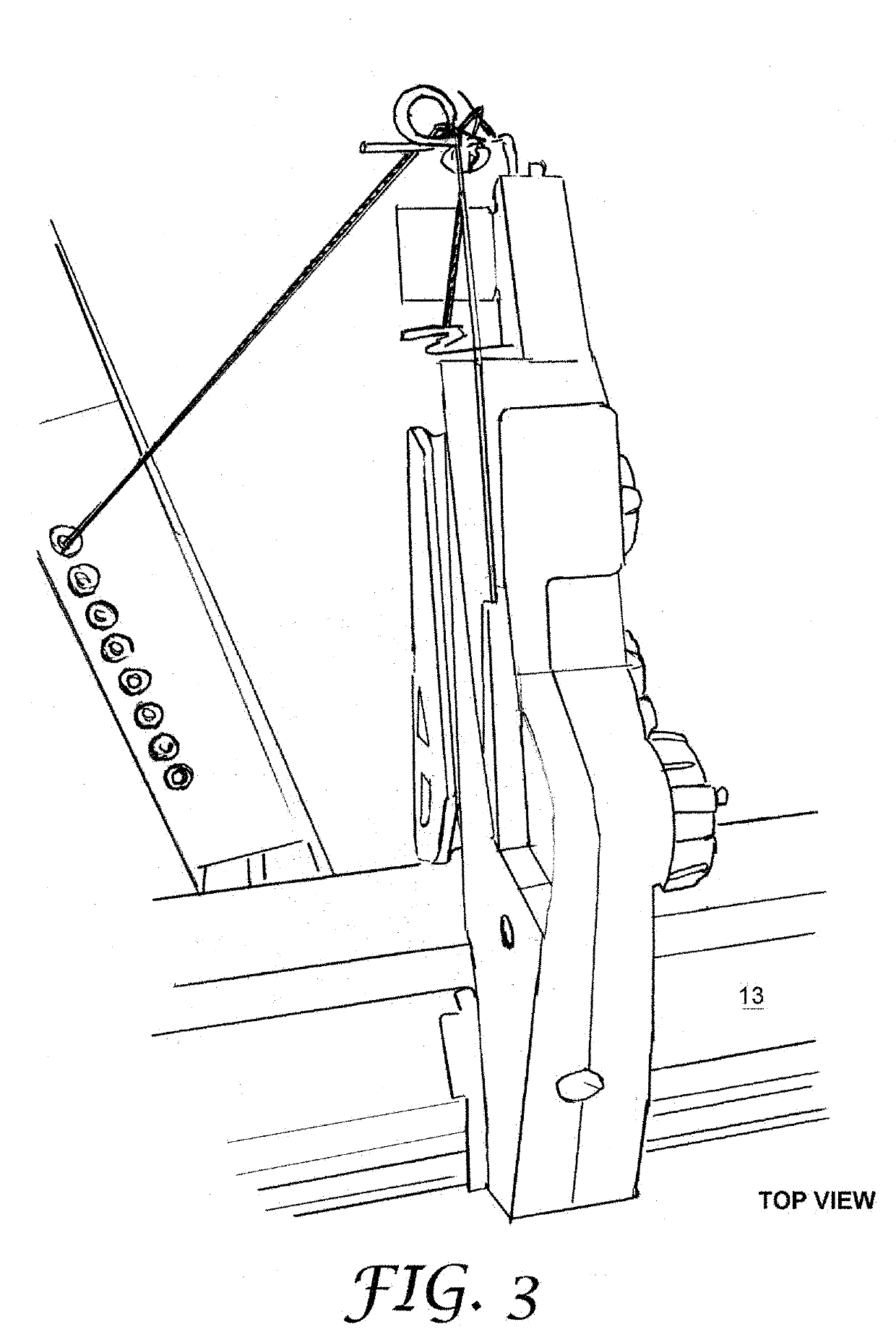
[0037]Embodiments of the present disclosure provide an automated unspooling mechanism on a textile machine that includes a feed device capable of controlling the tension of the knitting material and creating a variable deployment speed by which the material is unspooled from a cylinder-shaped package.

Problems solved by technology

Flat V-bed knitting machines create unique challenges.
Particularly, when feeding traditional materials into a flat V-bed machine in a knitting process, selected feeders may travel different distances on each traverse of the machine, may remain static for some periods of time in the knitting process, may start abruptly or come to sudden halts.
When they are deployed and fed to the machine for knitting, the materials tend to over spin, snag on flanges, and slide over itself.
This twist builds up as the material is deployed and creates a hard spot, containing excess twist in one section, typically resulting in the material work-hardening and breaking on itself.
When the machine stops, the cylinder continues to spin and the slack slides over itself, which can cause tanglement when the feed starts again.
The same packages, if mounted on a slanted or level horizontal spindle that is perpendicular to the machine as in circular stands or creels, pose the same torqueing problem.
Slanting the perpendicular spindles (package holders) adds to the tangling problem, with the materials sliding over themselves.
Slick materials (such as monofilaments and wires) slide down the spools over other wrapped strands of material, which usually causes a snag on the spool and stops the deployment of material.
The material may break at the needle in the machine or at the spool.
Conversely, strong materials can break machine parts, guides and needles, and stop motions.
Mounting the packages horizontal and parallel to the machine solves the torqueing problem, but this makes the packages difficult to start spinning during operation.
Sudden starts can break the material, sudden stops cause the issues of: an undesired unraveling; loose strands; tangling the material on the packaging; potential snagging on other parts of the equipment; loose material (slack) not wound back on to the spool; slack in the strand causing loose rows to be knitted in the next or several next fabric rows and resulting in inconsistent fabrication.
Conversely, restarting the cylindrical packaging in order to deploy material again after a machine stop or feeder pause can create tight rows in the next or several next fabric rows, resulting in inconsistent knitting.
Once a break has occurred in a material such a filament, there is no way to repair the knitted construction without producing an obvious defect.
The machine must be stopped, the end of the tangled mess found on the cylinder package must be located and restrung throughout the machine, which is a frustrating process.
There can be minutes, hours, or in the case of some composite materials, days already invested into the knitting process, as well as expensive materials.
However, this is problematic on textile equipment, specifically weft knitting or V-bed machines.
Starting a feeder can be a jerky motion, which is difficult for positive feed systems to manage precisely.
The angles required of a stiff or conductive material to pass through a standard OEM stop motion increase drag, risk of conductive charge build up, and the risk that a material may build a shape memory from the passages.
Abrasive materials such as ceramics, meta-aramids, and para-aramids for example, would create excessive wear on many of the guides, tensioning devices, and the pot eye.

Method used


Image

  • System and method of unspooling a material into a textile machine
  • System and method of unspooling a material into a textile machine
  • System and method of unspooling a material into a textile machine

Examples


Embodiment Construction

[0041]Reference will now be made in detail to the preferred embodiments of the present invention, examples of which are illustrated in the accompanying drawings. While the invention will be described in conjunction with the preferred embodiments, it will be understood that they are not intended to limit the invention to these embodiments. On the contrary, the invention is intended to cover alternatives, modifications and equivalents, which may be included within the spirit and scope of the invention as defined by the appended claims. Furthermore, in the following detailed description of embodiments of the present invention, numerous specific details are set forth in order to provide a thorough understanding of the present invention. However, it will be recognized by one of ordinary skill in the art that the present invention may be practiced without these specific details. In other instances, well-known methods, procedures, components, and circuits have not been described in detail ...


PUM


Abstract

An automated unspooling mechanism capable of dispensing of knitting material strands in a dynamically-controlled tension on a knitting machine. An unspooling device is configured to sense the tension of a strand fed to the knitting machine, and responsively adjust the strand deployment speed to avoid too little or too much strand dispensing without interrupting the knitting process. The unspooling device includes a variable motor drive that can rotate the strand package in various speeds, and a spring arm trigger that can sense the current tension of the dispensed material. The spring arm trigger can vary its arm position based on the sensed tension. The arm position is then processed and converted to a signal to vary the motor speed. Therefore, the deployment speed of the strands can be dynamically controlled based on a sensed tension of feeding the strand.

Description

CROSS REFERENCE TO RELATED APPLICATION[0001]This patent application claims priority and benefit of U.S. Provisional Patent Application No. 62 / 672,519, entitled “METHOD FOR UNSPOOLING A FIBER INTO A TEXTILE MACHINE,” filed on May 16, 2018, the entire content of which is herein incorporated by reference for all purposes.TECHNICAL FIELD[0002]Embodiments of the present disclosure relate generally to textile manufacturing machines, and more specifically, to the field of strand unspooling mechanisms on textile manufacturing machines.BACKGROUND OF THE INVENTION[0003]Most textile equipment is used for traditional textile manufacturing applications, such as apparel, and utilizes traditional yarns such as cotton, wool, polyester, nylon, elastics, and other common materials. OEM textile equipment is generally engineered to support the apparel industry. Modern textile machines, such as electronic knitting equipment, have variable speed motors driving the fabric making process. This is true for ...

Claims


Application Information

Patent Timeline
Patent Type & Authority Applications(United States)
IPC IPC(8): D04B15/48D04B15/44D04B15/99B65H49/20B65H59/02
CPCD04B15/99D04B15/44D04B15/48B65H59/02B65H49/20D04B35/14D04B15/40B65H59/04B65H59/387D04B15/46B65H59/385
Inventor HUFFA, BRUCEHUFFA, CONCETTA MARIA
Owner FABDESIGNS
Learn More