Method for detecting geological objects in a seismic image

a seismic image and object detection technology, applied in seismology, borehole/well accessories, instruments, etc., can solve the problems of difficult automatic implementation, limited performance, and inability to detect geological objects in seismic images,

a seismic image and object detection technology, applied in seismology, borehole/well accessories, instruments, etc., can solve the problems of difficult automatic implementation, limited performance, and inability to detect geological objects in seismic images,

US20190353811A1Active Publication Date: 2019-11-21INST FR DU PETROLE +2

Image

  • Method for detecting geological objects in a seismic image
  • Method for detecting geological objects in a seismic image
  • Method for detecting geological objects in a seismic image

Examples


embodiment examples

[0181]The features and advantages of the method according to the invention will become more clearly apparent from studying the following application examples.

first example

[0182]In this example it is a question of illustrating, using a purely theoretical example, the principle of the method according to the invention.

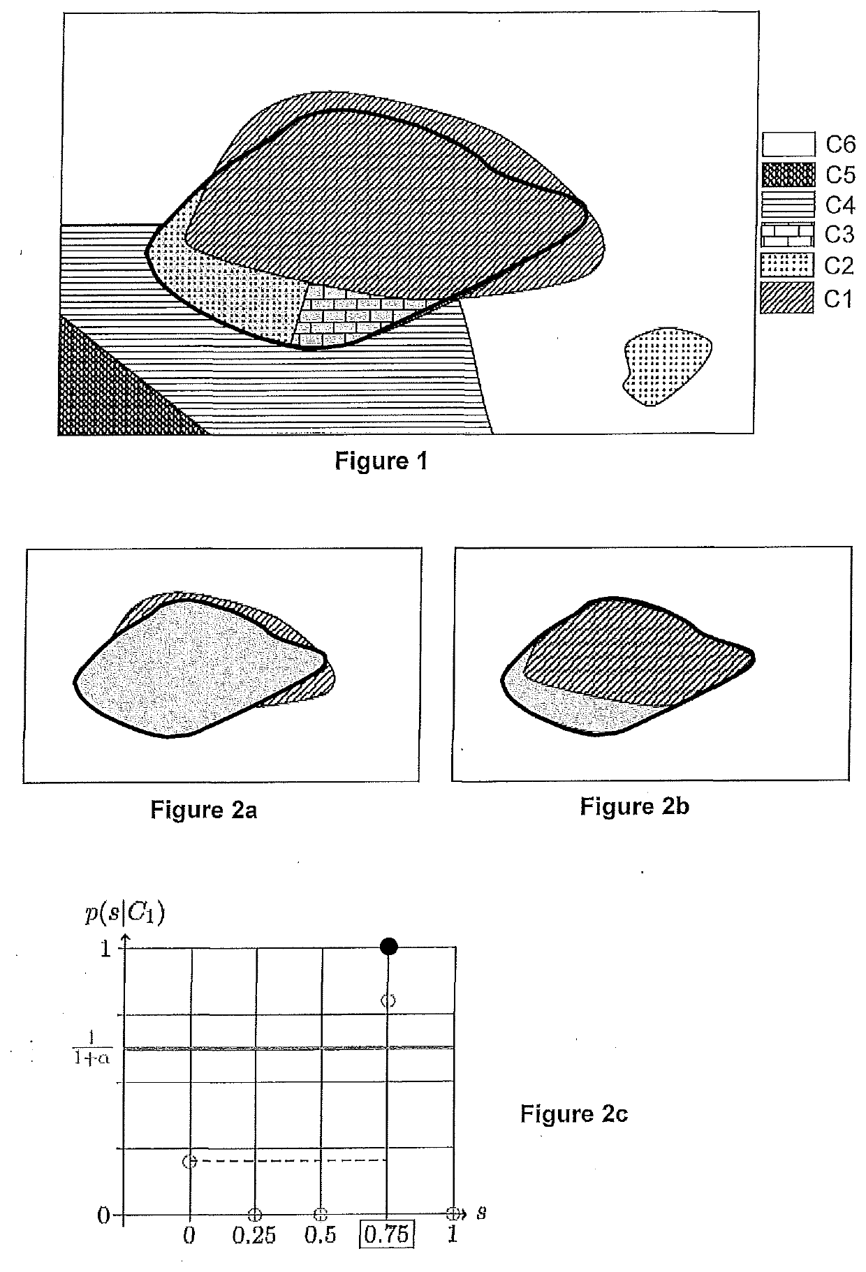
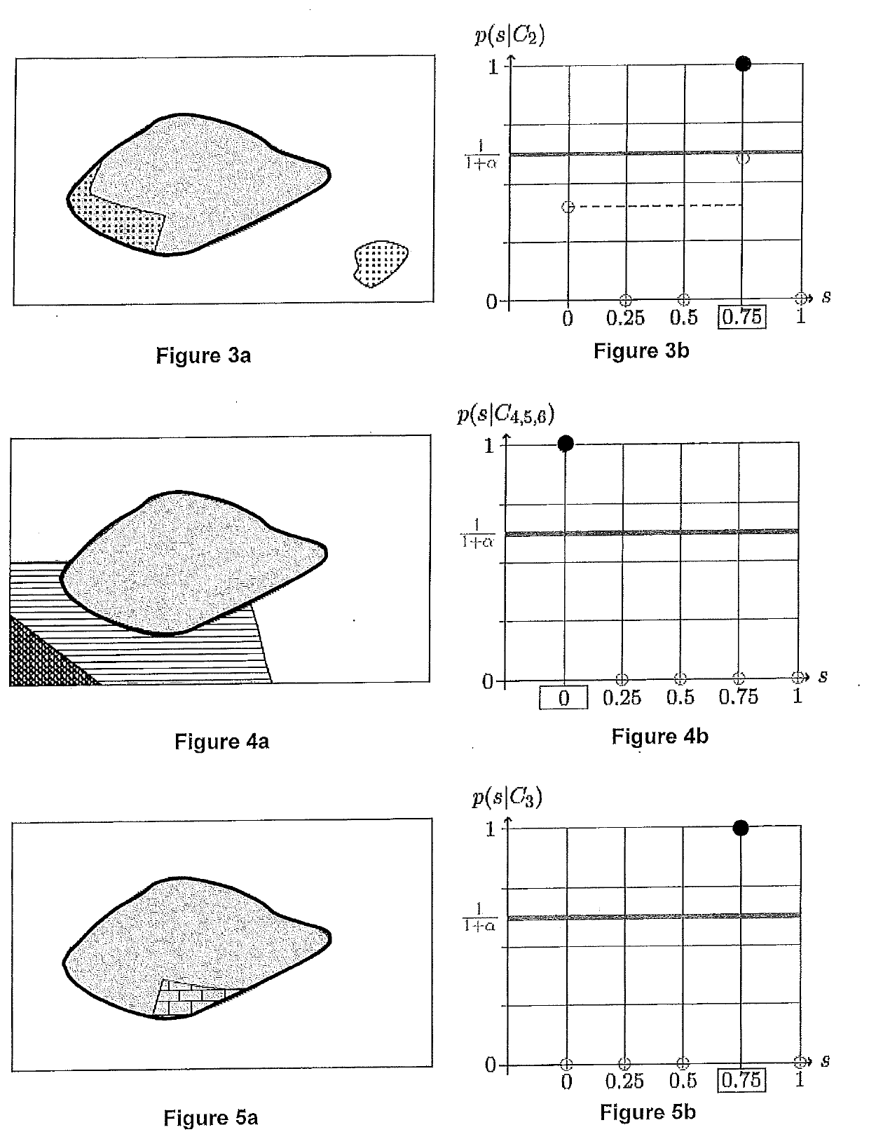
[0183]FIG. 1 shows a geological object (bold outline) which has been manually delimited in a seismic image, along with the classes (classes C1 to C6) resulting from the application of an applied classification method. The a priori probabilities are discretized as follows [s1,s2,s3,s4,s5]=[0, 0.25, 0.5, 0.75, 1]. The probability s4 has been attributed to the interior of the outlined zone, and the probability s1 has been attributed to the samples outside this outline. Thus, for this example, only two probability values are shown in the overall distribution of a priori probabilities.

[0184]In this example, the risk of having forgotten to interpret a geological object of the sought type in the seismic image is considered to be around 40%. According to the embodiment defined above, this amounts to setting α=0.6 (recall that α=1 corresponds to t...

second example

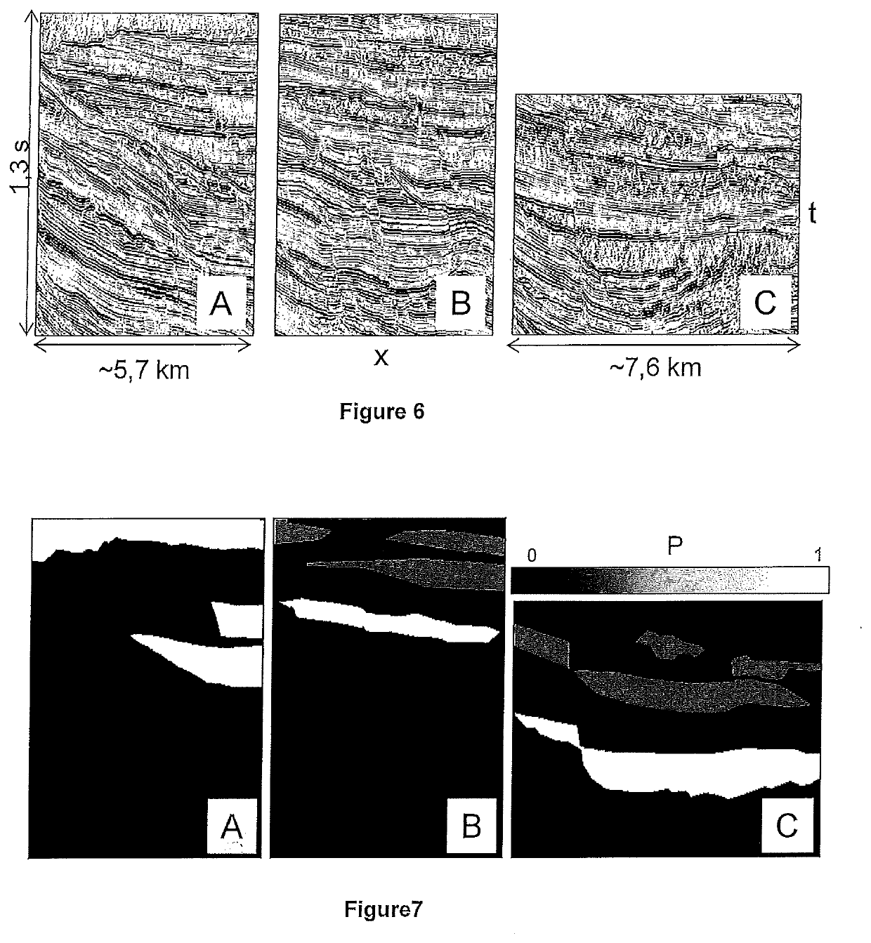
[0195]For this example, the geological objects are to be delimited in a 3D seismic image (a 3D seismic cube after stacking, also called a “post-stack” seismic cube) and correspond to MTD (mass-transport deposit)-type sedimentary deposits. These objects can be recognized in the seismic image by an informed interpreter by the various seismic facies that they contain and their arrangement. The seismic image has a vertical sampling interval of 4 ms, and an intertrace distance of 25 m in both (crossline and inline) directions. The MTDs that it is sought to detect have a size of several tens of kilometres laterally, and are at most 100 ms thick. Three 2D sections of the cube are used as learning seismic images (see FIG. 6, which shows these three learning seismic images A, B and C). A pixel of a seismic image therefore has a size of 4 ms×25 m. These three seismic sections have been interpreted by an interpreter, who has delimited zones with a very high a priori probability of belonging P ...


PUM


Abstract

The invention is a method applicable to oil and gas exploration and exploitation for automatically detecting geological objects belonging to a given type of geological object in a seismic image, on a basis of a priori probabilities of belonging to a type of geological object assigned to each of samples of the image to be interpreted. The image is transformed into seismic attributes applied beforehand, followed by a classification method. For each of the classes, an a posteriori probability of belonging to a type of geological object is determined for each of the samples of the class according to the a priori probabilities, of the class, of belonging, and according to a parameter α describing a confidence in the a priori probabilities of belonging. Based on the class of the sample, the determined a posteriori probability of belonging to a type of geological object is assigned for the samples of the class. The geological objects belonging to the type of geological object are detected based on determined of the a posteriori probabilities of belonging to the type of geological object for each of the samples of the image to be interpreted.

Description

CROSS REFERENCE TO RELATED APPLICATIONS[0001]Reference is made French Application No. 18 / 54.190 filed May 18, 2018, which are incorporated herein by reference in their entirety.BACKGROUND OF THE INVENTIONField of the Invention[0002]The present invention relates to the field of exploring for and exploiting a fluid contained in a subterranean formation. In particular, the present invention relates to the field of exploring for and exploiting hydrocarbons that are present in a subterranean formation, or else to the field of exploring a subterranean formation with a view to geologically storing a fluid such as CO2, or else to the field of monitoring a site at which a fluid is geologically stored.Description of the Prior Art[0003]Oil and / or gas exploration searches for hydrocarbon deposits within a sedimentary basin. The understanding of the principles of hydrocarbon formation and the relationships between hydrocarbons and the geological history of the ground has made it possible to deve...

Claims


Application Information

Patent Timeline
21 Nov 2019
Publication
US20190353811A1
IPC
G01V1/30; E21B41/00; E21B49/00
CPC
E21B41/0092; E21B49/00; G01V1/301; G01V1/32; E21B41/00; G01V1/302; G01V1/307; G01V2210/641
Inventors
LE BOUTEILLER, PAULINE; CHARLETY, JEAN