
Image processing method based on peripheral reduction of contrast

a processing method and peripheral technology, applied in image enhancement, image analysis, instruments, etc., can solve the problem that a near-eye display or a tv display device is more likely to cause flicker

Active Publication Date: 2019-11-21
INTERDIGITAL MADISON PATENT HLDG SAS
View PDF0 Cites 1 Cited by
  • Summary
  • Abstract
  • Description
  • Claims
  • Application Information

AI Technical Summary

Benefits of technology

The invention aims to improve the display of videos on large screens by reducing the contrast of pixels. This involves reducing the luminance values of the highest pixels while increasing the luminance values of the smallest pixels. This technique helps to make the video look better on larger screens and avoids the need for adjustments to the video's content.

Problems solved by technology

Therefore, a large screen of a TV display device or a near-eye display is more likely to cause flicker.
This problem is more critical today because screens of large size are more widely used.

Method used


Image

  • Image processing method based on peripheral reduction of contrast
  • Image processing method based on peripheral reduction of contrast
  • Image processing method based on peripheral reduction of contrast

Examples


first embodiment

[0040]the method for processing images of a video sequence will now be described in reference to FIG. 9, in the context of displaying these images on a screen of a display device, having a width L and a height H.

[0041]Images of the video sequence are all defined in a same geometrical format, here a rectangular format delimited by a top and a bottom horizontal side of width L and a left and a right vertical side of height H. The horizontal sides are larger than the vertical sides.

[0042]In a first step of this first embodiment, peripheral areas of images are defined, preferably at least one peripheral area PL on the left side and at least one peripheral area PR on the right side.

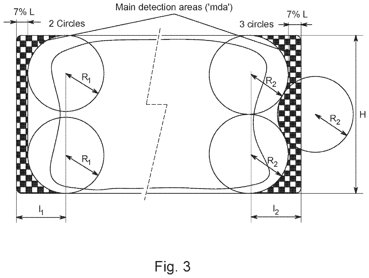
[0043]In a first variant of this first step illustrated on the left part of FIG. 3, the inner border of this peripheral area is anchored on four circles of radius R1 that are disposed symmetrically in reference to the center of the image, each tangent to a horizontal side of the image and centered at a given d...

second embodiment

[0076]In the method for processing images of a video sequence illustrated on FIG. 9 too, the peripheral areas are divided in N subregions 1, 2, . . . , i, . . . , N.

[0077]In an example, these subregions are identical squared areas, each of then having a side for instance equal to 3.%*L, where L is the width of the image.

[0078]Then, a contrast value Ri is computed for each subregion i, providing then a local contrast value for this subregion.

[0079]The local contrast Ri of a subregion i is for instance based on a ratio defined as:

[0080]the difference L1090 between the lowest luminance of the last decile of the distribution of luminance values of all pixels of this subregion and the highest luminance of the first decile of this distribution,

[0081]divided by the difference L100% between the highest luminance and the lowest luminance of this distribution,

[0082]wherein the last decile corresponds to the highest luminance values of the distribution and the first decile corresponds to the l...


PUM


Abstract

An object of the invention is to avoid or at least limit the aforementioned drawback by a specific processing of video images to display, notably on large size screens. For this purpose, a method for processing at least one image of a video sequence is described. The method includes defining at least two peripheral areas PL, PR in the at least one image, and reducing contrast of pixels in the defined peripheral area(s) having a local contrast RL and / or RD above a local contrast threshold Rth or reducing contrast of pixels in subregions 1, 2, . . . , i, . . . , N of these defined peripheral areas having a local contrast Ri, R′i above a local contrast threshold Ri-th.

Description

REFERENCE TO RELATED EUROPEAN APPLICATION[0001]This application claims priority from European Patent Application No. 18305596.1, entitled “IMAGE PROCESSING METHOD BASED ON PERIPHERAL REDUCTION OF CONTRAST”, filed on May 15, 2018, the contents of which are hereby incorporated by reference in its entirety.TECHNICAL FIELD[0002]The invention relates to the reduction of flickering of images in the peripheral region of the eyes.BACKGROUND ART[0003]In the context of foveal-peripheral vision, the temporal response of the Human Visual System (HVS) is not homogeneous across the visual field of the human eye. In terms of motion responsiveness of the eye, the peripheral region of the retina is known to be more sensitive to moving targets than the fovea region.[0004]The HVS response to spatial and temporal variations is commonly described by spatio-temporal Contrast Sensitivity Functions (CSF) which generally peak at certain spatial and temporal frequencies.[0005]For a given flickering light sou...

Claims


Application Information

Patent Timeline
IPC IPC(8): G09G3/20G09G5/10G09G3/36
CPCG09G5/10G09G2320/0247G09G2320/0276G09G2320/0266G09G3/3611G09G3/2003G06F3/14G06T5/40G06T2207/10016G06T2207/10024G09G3/20G09G2310/0232G09G2320/066G09G2320/0686G09G2360/16G06T5/94
Inventor MORIN, THOMASFRALEU, SEBASTIENQUERRE, GOULVEN
Owner INTERDIGITAL MADISON PATENT HLDG SAS
Learn More