Supercharge Your Innovation With Domain-Expert AI Agents!

System for transferring micro LED

a technology of light-emitting diodes and systems, which is applied in the direction of electrical components, semiconductor devices, electrical apparatus, etc., can solve the problems of damage to micro leds, each of the proposed techniques has some problems, and it is difficult to use a conventional pick-and-place machine, etc., and achieve the effect of efficient transfer of micro leds

Active Publication Date: 2019-11-21
POINT ENG
View PDF0 Cites 1 Cited by
  • Summary
  • Abstract
  • Description
  • Claims
  • Application Information

AI Technical Summary

Benefits of technology

The present invention describes a system that can better transfer small LEDs that are dropped in a solution. This means that the system can pick up and use these LEDs more efficiently.

Problems solved by technology

Particularly, with regard to the transfer of the micro LED device to a display substrate, as the LED size is reduced to 1 μm to 100 μm, it is impossible to use a conventional pick-and-place machine, and a technology of a transfer head for higher precision is required.
With respect to such a technology of a transfer head, several structures have been proposed as described below, but each of the proposed techniques has some problems.
However, this method may cause damage to micro LEDs due to electrification caused by the voltage applied to the head portion during induction of static electricity.
However, in the Related Art 4, it is difficult to manufacture a ciliary adhesive structure.
However, the Related Art 5 has a problem in that continuous use of the adhesive is required, and the micro LED may be damaged when pressed with the roller.
However, the Related Art 6 has a problem in that a solution is required since the micro LED is immersed in the solution to transfer to the array substrate, and a drying process is required.
However, the Related Art 7 has a problem in that a process of applying a bonding material to the pick-up heads is required because the bonding material having an adhesive force is required to be applied to bonding surfaces of the multiple pick-up heads to transfer the micro LED.
However, there is a limit to solving the problems because such problems are derived from the basic principles adopted in the related arts.

Method used


Image

  • System for transferring micro LED
  • System for transferring micro LED
  • System for transferring micro LED

Examples


first embodiment

[0089]Hereinbelow, a system for transferring a micro LED according to a first embodiment of the present invention will be described with reference to FIGS. 3A to 6C.

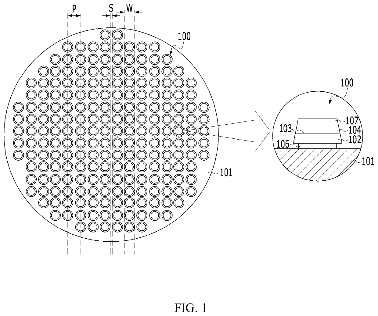
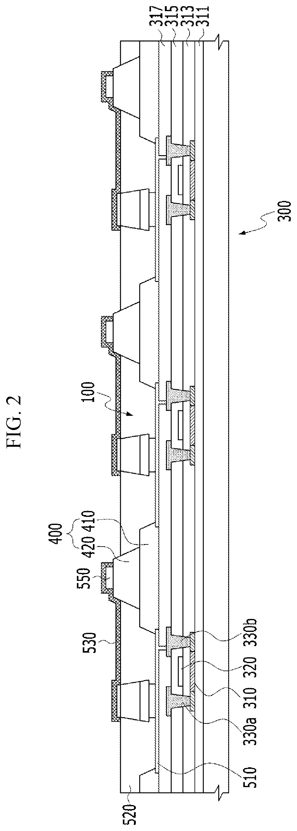
[0090]The micro LEDs 100 manufactured on the growth substrate 101 are separated from the growth substrate 101 and then transferred to the display substrate 300 through at least one transfer process.

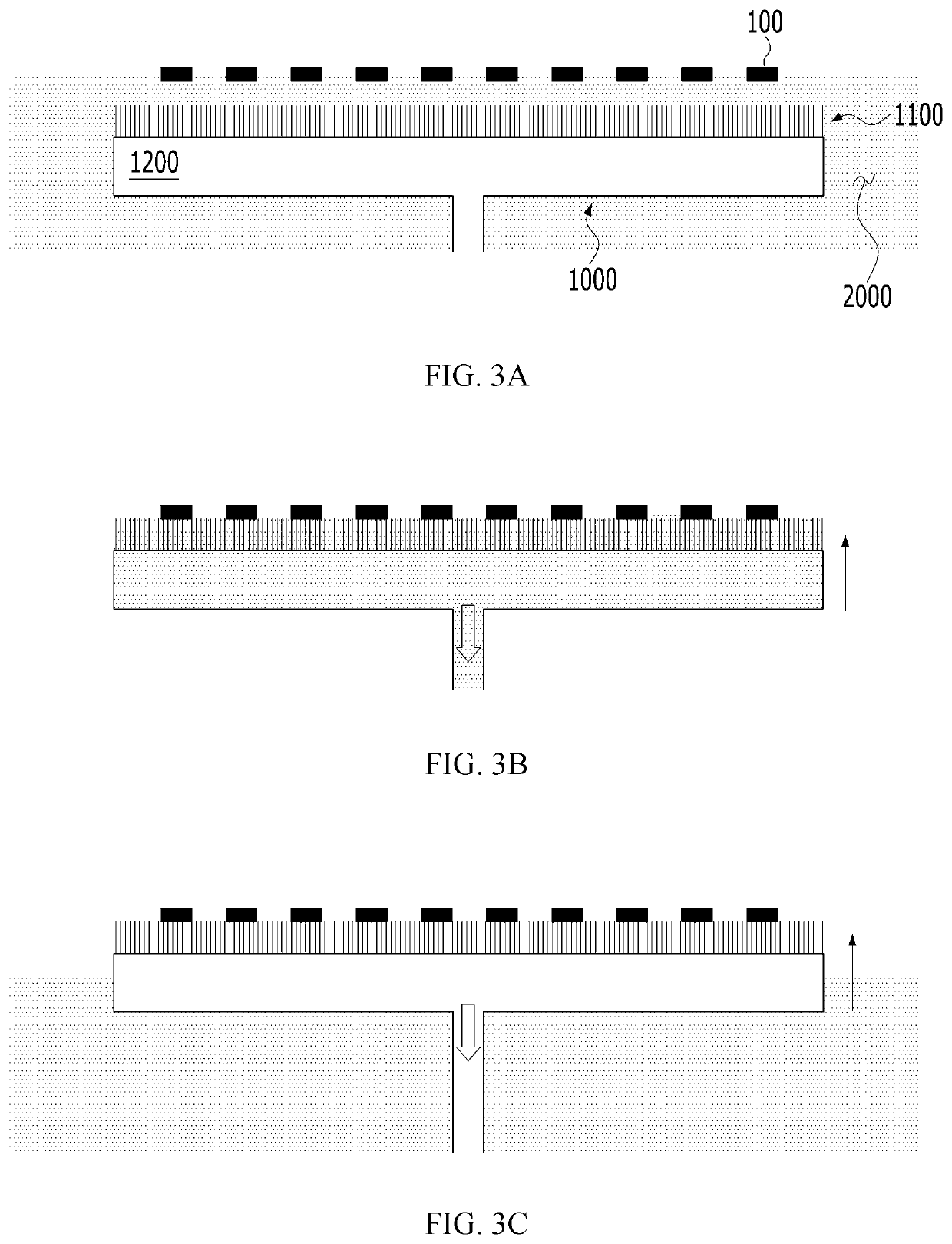
[0091]The micro LEDs 100 manufactured on the growth substrate 101 are dropped in a reservoir containing a solution 2000 before being transferred to the display substrate 300.

[0092]The micro LEDs 100 may float in the solution 2000 or sink into the solution 2000 depending on the density difference between the micro LEDs 100 and the solution 2000. The system for transferring a micro LED according to the first embodiment of the present invention includes a structure that can be applied to the system regardless of the density difference between the micro LEDs 100 and the solution 2000 or another structure that can be applied to the...

second embodiment

[0125]Hereinbelow, a system for transferring a micro LED according to a second embodiment of the present invention will be described with reference to FIGS. 7A to 10C.

[0126]The system for transferring a micro LED according to the second embodiment differs from the system for transferring a micro LED according to the first embodiment in that the system according to the second embodiment is configured such that the micro LED grip body 1000 is provided with an electroosmotic pump and grips the micro LEDs 100 according to the operation of the electroosmotic pump, whereas the system according to the first embodiment is configured such that the vacuum pump is operated to grip the micro LEDs 100.

[0127]The electroosmotic pump, abbreviated as EO pump, is a pump that moves a fluid by using an electroosmosis generated when voltage or electricity is applied to an electrode provided on or formed in the porous member 1100. The porous member 1100 is made of a porous material having pores in which ...


PUM

PropertyMeasurementUnit
sizeaaaaaaaaaa
wavelength rangeaaaaaaaaaa
pore diameteraaaaaaaaaa

Abstract

The present invention provides a system for transferring a micro LED, the system transferring more efficiently a micro LED dropped in a solution.

Description

CROSS REFERENCE TO RELATED APPLICATION[0001]The present application claims priority to Korean Patent Application No. 10-2018-0056013 filed May 16, 2018, the entire contents of which is incorporated herein for all purposes by this reference.BACKGROUND OF THE INVENTIONField of the Invention[0002]The present invention relates to a system for transferring a micro light-emitting diode (micro LED).Description of the Related Art[0003]Currently, the display market is still dominated by LCDs, but OLEDs are quickly replacing LCDs and emerging as mainstream products. In a current situation where display makers are rushing to participate in the OLED market, micro light-emitting diode (hereinafter, referred to as micro LED) displays have emerged as another next-generation display. Liquid crystal and organic materials are the core materials of LCDs and OLEDs, respectively, whereas the micro LED display uses 1 μm to 100 μm of an LED chip itself as light emitting material.[0004]Since the term “micr...

Claims


Application Information

Patent Timeline
Patent Type & Authority Applications(United States)
IPC IPC(8): H05K13/04H01L27/32H01L33/36H01L33/08H01L33/00
CPCH01L27/3272H01L33/005H01L33/36H05K13/0409H01L33/08H01L27/156H01L21/67144H01L21/6838H01L25/0753H01L2933/0033H01L33/486Y10T29/53191H10K59/126
Inventor AHN, BUM MOPARK, SEUNG HOBYUN, SUNG HYUN
Owner POINT ENG
Features
  • R&D
  • Intellectual Property
  • Life Sciences
  • Materials
  • Tech Scout
  • Unparalleled Data Quality
  • Higher Quality Content
  • 60% Fewer Hallucinations
Learn More