Adjustable fertilizer application implement

a technology of fertilizer and implement, which is applied in the direction of direct liquid fertilizer delivery, furrow making/covering, agriculture, etc., can solve the problems of poor plant health and growth, difficult fertilizer placement, uneven soil conditions, etc., and achieve the effect of preventing pinch points and facilitating the flow of residu

Active Publication Date: 2019-11-28
AG FOCUS LLC
View PDF5 Cites 0 Cited by
  • Summary
  • Abstract
  • Description
  • Claims
  • Application Information

AI Technical Summary

Benefits of technology

[0010]The disc of the preferred embodiment is concave and angled outwardly to squeeze the soil together to create a groove with a firm wall. The discs are offset to facilitate the flow of residue and prevent pinch points.

Problems solved by technology

The problem is that soil conditions are not uniform due to for example weather, location and general conditioning.
This makes accurate placement of fertilizer difficult because furrow forming discs are statically mounted; they cannot be adjusted during the fertilizer operation.
In other words, the depth of penetration of the furrow forming discs is not adjustable on the fly, resulting in varied depths and poor plant health and growth.

Method used


Image

  • Adjustable fertilizer application implement
  • Adjustable fertilizer application implement
  • Adjustable fertilizer application implement

Examples


Embodiment Construction

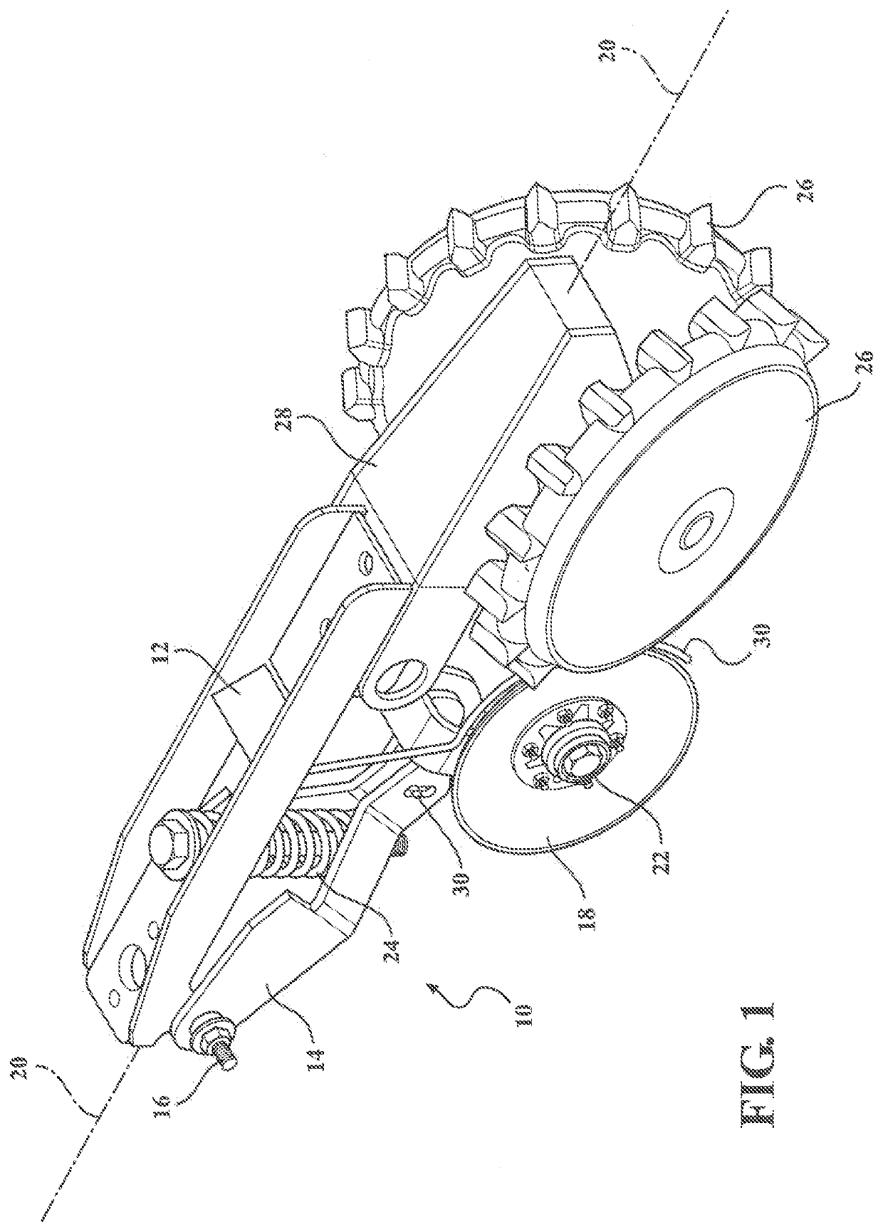
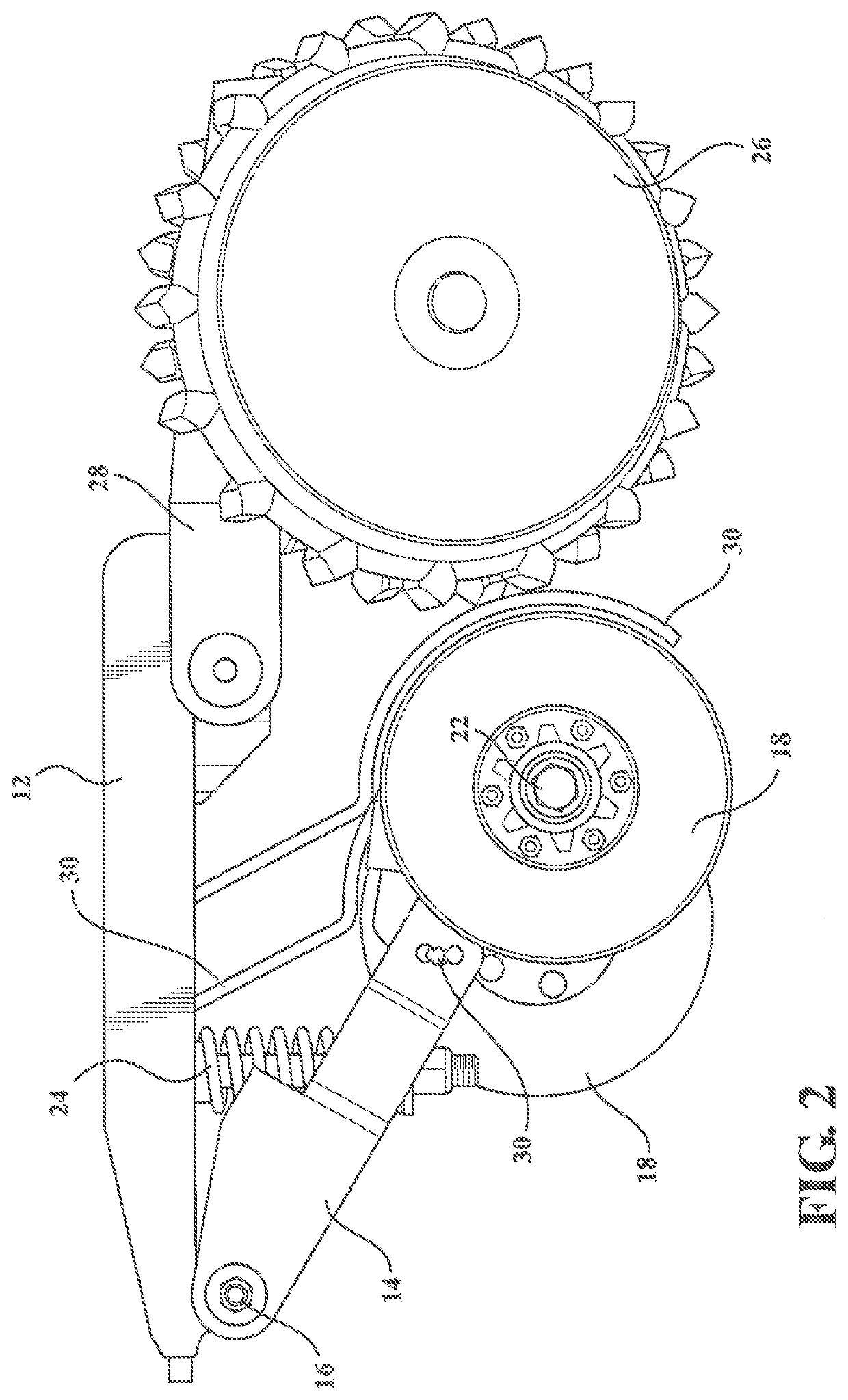
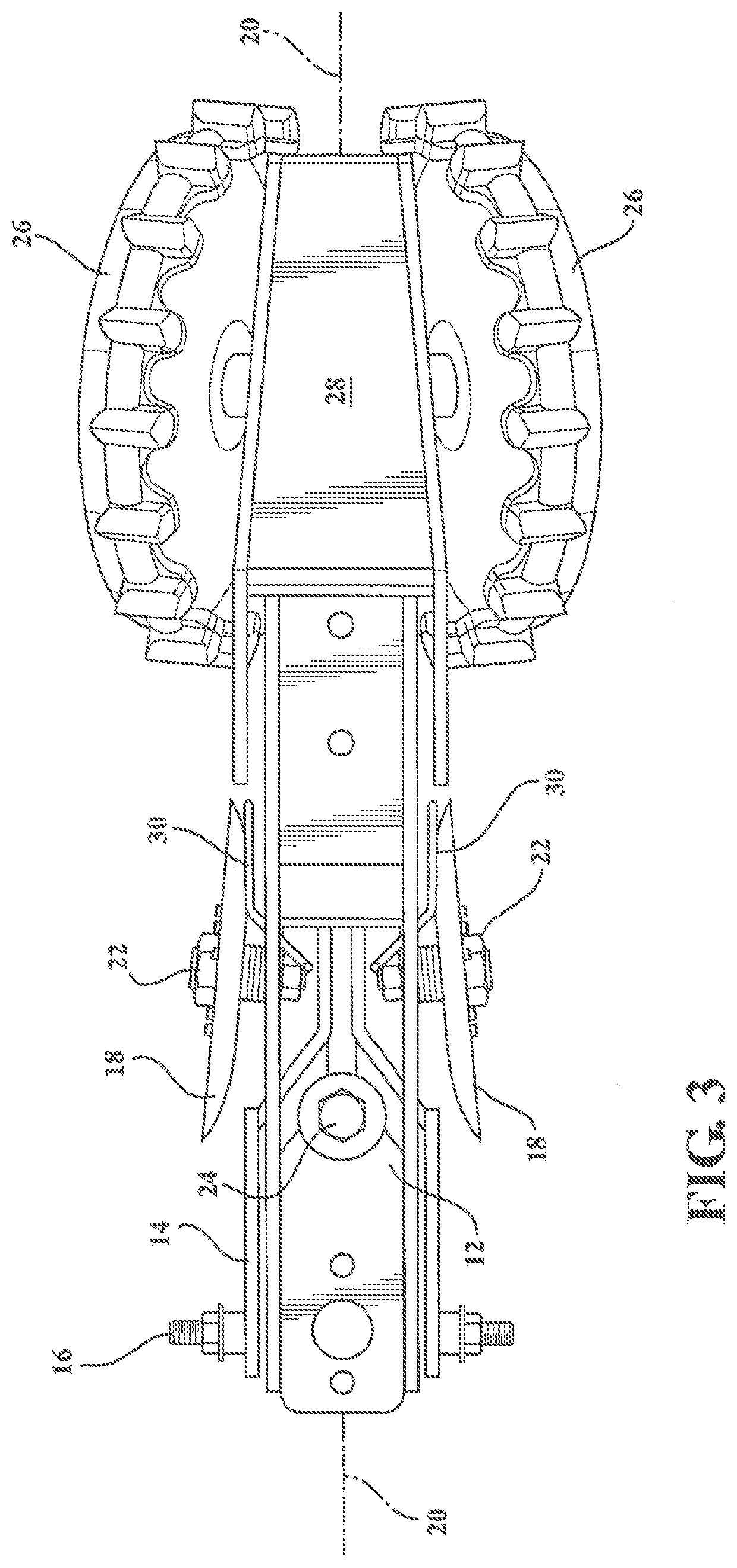
[0017]Generally shown in the figures is the fertilizer application implement 10 of the present invention. The fertilizer application implement 10 has a main frame 12 for connecting the system to agricultural equipment such as for example a seed planter.

[0018]Pivotally connected to the main frame 12 is a swing arm 14. A pivot 16 connects the swing arm 14 to the frame 12. Mounted at the free end of the swing arm 14 are discs 18. Discs 18 rotate about an axle 22. As illustrated, the discs 18 are each concave and offset in a direction parallel with the centerline 20. In addition, the discs 18 angle outwardly in the direction of travel with respect to the centerline 20, see FIG. 3.

[0019]An actuator 24 connects the swing arm 14 to the frame 12. The actuator 24 can be spring biased, hydraulic, electric, pneumatic, etc. The actuator 24 allows the position of the swing arm and thereby the discs 18 to be adjusted for a particular depth of penetration.

[0020]The actuator 24 can be remotely oper...


PUM


Abstract

The present invention discloses an agricultural implement for applying fertilizer beneath the surface of the soil. The implement has a main frame for connecting the agricultural implement to agricultural equipment. A swing arm is pivotally connected to the main frame. An adjustable actuator interconnects the swing arm to the main frame to control the movement of the swing arm with respect to the main frame. A pair of discs are mounted to the free end of the swing arm for rotation with respect to the swing arm. The discs are offset mounted with respect to one another and are angled outwardly with respect to the direction of travel of the implement. The discs form grooves for receipt of fertilizer. Fertilizer tubes are mounted adjacent the discs and terminate behind the discs with respect to the direction of travel. The fertilizer tubes deposit fertilizer in the grooves formed by the discs. A furrow closer is attached to the main frame to close the groove opened by the discs.

Description

RELATED APPLICATIONS[0001]This application claims benefit to United States Provisional Application No. 62 / 675,310 filed on May 23, 2018 which is incorporated herein by reference in its entirety.STATEMENT REGARDING FEDERALLY SPONSORED RESEARCH[0002]NONE.TECHNICAL FIELD[0003]This invention relates generally to agricultural equipment and more specifically to a fertilizer application implement for applying fertilizer below the soil surface.BACKGROUND OF THE INVENTION[0004]As is well known, application of fertilizer to plants is critical to their healthy growth. Proper nutrition is essential for satisfactory crop growth and production. Fertilizer placement is an integral part of efficient crop management. “Correct placement often improves the efficiency by which plants take up nutrients and consequently encourages maximum yields of intensively managed agronomic crops. Correct fertilizer placement is especially critical for maximum crop yields under reduced tillage operations.” (See Unive...

Claims


Application Information

Patent Timeline
Patent Type & Authority Applications(United States)
IPC IPC(8): A01C23/02A01C5/06
CPCA01C23/02A01C5/064A01C5/068A01C23/025
Inventor FREED, BRUCE W.FREED, BRIAN E.
Owner AG FOCUS LLC
Why Eureka
Try Eureka