
Multi-direction proton therapy apparatus and method of use thereof

a proton therapy and multi-direction technology, applied in the field of cancer therapy imaging and/or treatment apparatus, can solve the problems of reducing the ability to repair damaged dna, affecting the healing effect of patients, and being particularly vulnerable to attack on their dna

Active Publication Date: 2019-11-28
PROTOM INT HLDG CORP
View PDF5 Cites 2 Cited by
  • Summary
  • Abstract
  • Description
  • Claims
  • Application Information

AI Technical Summary

Benefits of technology

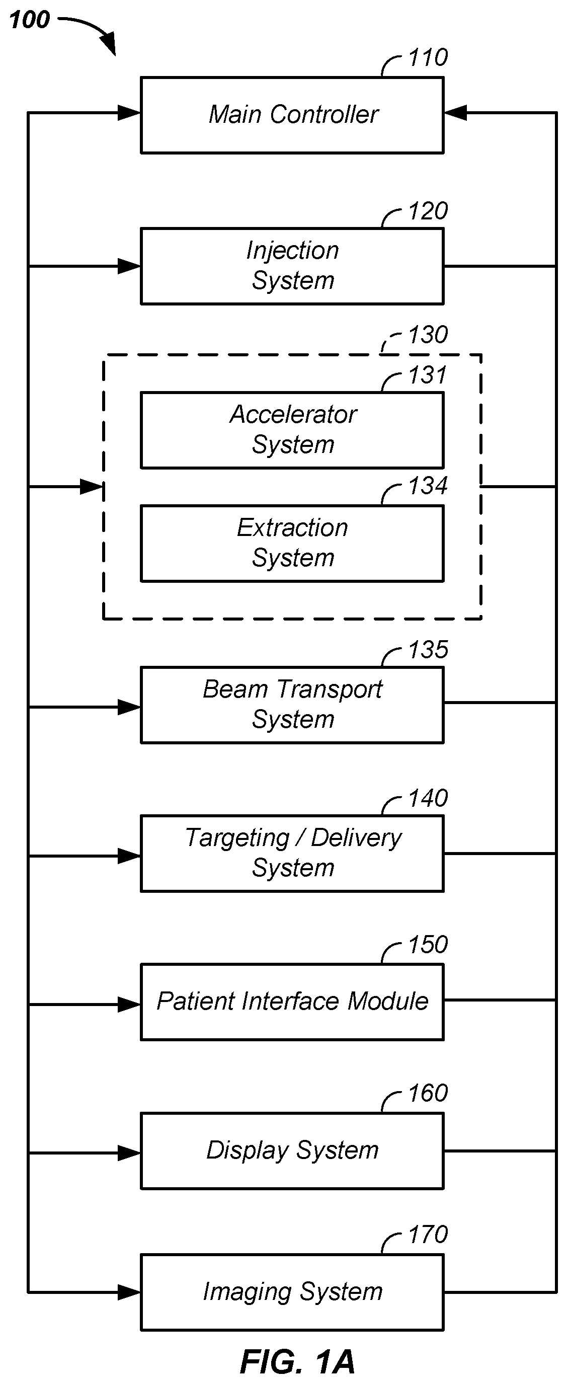
This patent is for a system that uses multiple beams of charged particles to treat cancer. The system has several technical benefits, including improved targeting of cancer cells and reduced side effects on healthy tissues.

Problems solved by technology

These particles damage the DNA of cells, ultimately causing their death.
Cancerous cells, because of their high rate of division and their reduced ability to repair damaged DNA, are particularly vulnerable to attack on their DNA.

Method used


Image

  • Multi-direction proton therapy apparatus and method of use thereof
  • Multi-direction proton therapy apparatus and method of use thereof
  • Multi-direction proton therapy apparatus and method of use thereof

Examples


example viii

[0331]In an eighth example, an actual position of the cantilevered rotatable gantry system is monitored, determined, and / or confirmed using the fiducial indicators 2040, described, infra, such as a fiducial source and / or a fiducial detector / marker placed on any section of the gantry 490, patient positioning system 1350, and / or patient 230.

[0332]Floor Force Directed Gantry System

[0333]Referring now to FIG. 17, a wall mounted gantry system 1700 is illustrated, where a wall mounted gantry 499 is bolted to a first wall 1710, such as a first buttress, with a first set of bolts 1714, optionally using a first mounting element 1712, and mounted to a second wall 1720, such as a second buttress 1720, such a through a second mounting element 1722, with a second set of bolts 1714. The inventor notes that in this design, forces, such as a first force, F1, and a second force, F2, are directed outward into the first wall 1710 and the second wall 1720, respectively, where at least twenty percent of...

example i

[0505]In a first example, sections of individual treatment plans are combined to form the multi-modality treatment plan 5040. Generally, in the first example individual treatment plans, such as outputs from a traditional single treatment beam type treatment planning system (TPS), are combined or sections of the individual treatment plans are combined to form the multi-modality treatment plan 5040, where each of the treatment plans is for an individual beam type. More particularly, using the first beam type 5012, such as using a proton, a first treatment plan is developed; a second beam type 5014, such as a carbon particle, is used to develop a second treatment plan; a third beam type 5016, such as a helium particle or a neon particle beam, is used to develop a third treatment plan, and / or an nth treatment plan is developed using the nth beam type 5018. In one case, the multi-modality treatment plan 5040 selects treatment elements from each of the n treatment plans to treat the tumor...

example ii

[0506]In a second example, the multi-modality treatment plan 5040 is directly formed using the multiple beam types 5010. Thus, instead of a traditional treatment planning system (TPS) using a single beam type, a multi-modal treatment planning system (M-TPS) is used that develops a tumor treatment plan using more than one beam type. As described, supra, optionally and preferably, the multi-modal treatment planning system incorporates dose delivery information along treatment beam paths along with scattering, dispersion, and / or delivery dosage errors along the treatment beam paths to yield a prescribed, generally uniformly distributed, tumor irradiation plan.


PUM


Abstract

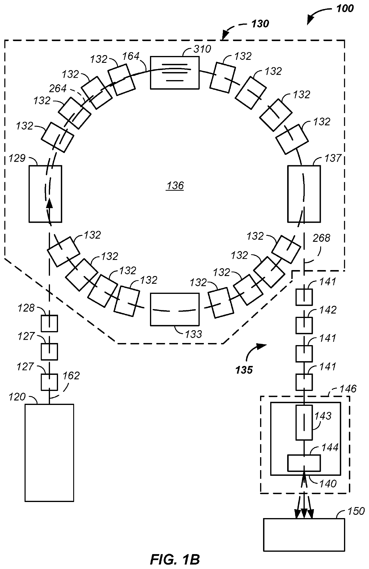
The invention comprises a method and apparatus for treating a tumor of a patient, in a beam treatment center comprising a floor, with positively charged particles, comprising: (1) a synchrotron mounted to an elevated floor section above the floor of the beam treatment center; (2) a beam transport system, comprising: at least three fixed-position beam transport lines, where none of the synchrotron and the beam transport system penetrate through the floor of the beam treatment center; (3) the positively charged particles transported from the synchrotron, through the beam transport system, to a position above a patient positioning system during use; and (4) an optional repositionable nozzle system connected to a first, second, and third fixed-position beam transport line at a first, second, and third time, respectively, where the nozzle track forms an arc of a circle and the repositionable nozzle system moves along the nozzle track.

Description

CROSS-REFERENCES TO RELATED APPLICATIONS[0001]This application is a continuation-in-part of U.S. patent application Ser. No. 15 / 901,788 filed Feb. 21, 2018, which is a continuation-in-part of U.S. patent application Ser. No. 15 / 892,240 filed Feb. 8, 2018, which is:[0002]a continuation-in-part of U.S. patent application Ser. No. 15 / 838,072 filed Dec. 11, 2017, which is a continuation-in-part of U.S. patent application Ser. No. 15 / 823,148 filed Nov. 27, 2017, which is a continuation-in-part of U.S. patent application Ser. No. 15 / 467,840 filed Mar. 23, 2017, which is a continuation-in-part of U.S. patent application Ser. No. 15 / 402,739 filed Jan. 10, 2017, which is a continuation-in-part of U.S. patent application Ser. No. 15 / 348,625 filed Nov. 10, 2016, which is a continuation-in-part of U.S. patent application Ser. No. 15 / 167,617 filed May 27, 2016; and[0003]a continuation-in-part of U.S. patent application Ser. No. 15 / 868,897 filed Jan. 11, 2018, which is a continuation of U.S. pate...

Claims


Application Information

Patent Timeline
IPC IPC(8): A61N5/10G21K1/093A61B6/03G21K5/04G21K1/087
CPCA61N5/107H01J35/14A61N5/1044A61B6/03G21K1/087A61N5/1082A61N2005/1087G21K1/093G21K5/04A61N5/1067A61N2005/1097A61N2005/1074A61N5/1077A61B6/032A61B6/037A61B6/0407A61B6/4092A61B6/4233A61B6/4241A61B6/4258A61B6/4417A61B6/487G21K5/10
Inventor RAYMOND, DANIEL J.LEE, W. DAVISBENNETT, JAMES P.
Owner PROTOM INT HLDG CORP
Learn More