

Hydraulic door closer with fluid overflow chamber
- Summary
- Abstract
- Description
- Claims
- Application Information
AI Technical Summary
Benefits of technology
Problems solved by technology
Method used
Image

Examples
Embodiment Construction
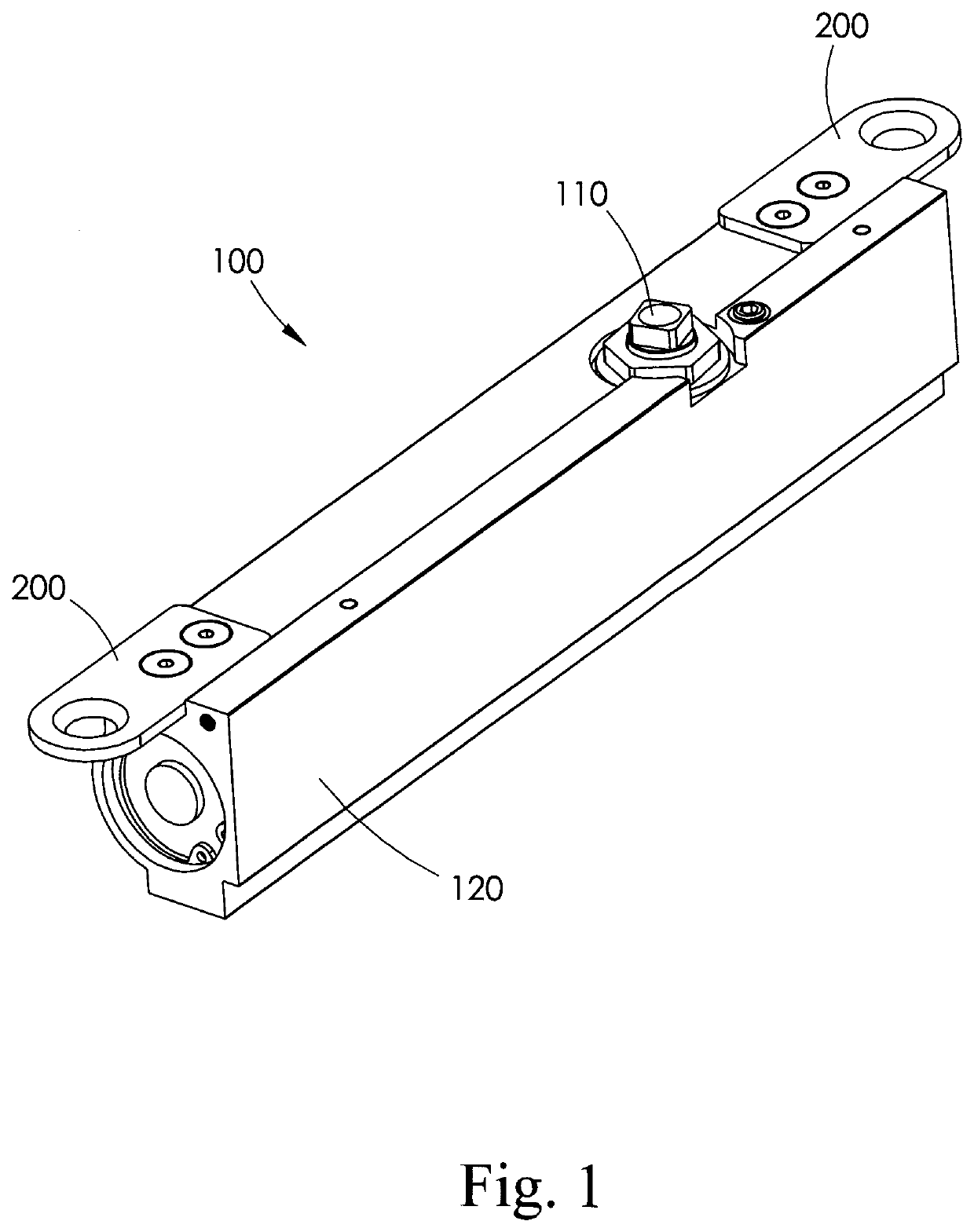
[0043]The disclosed hydraulic door closer having an overflow chamber or reservoir is particularly intended for use in a hydraulic door closer for a storm or screen door, but may provide useful benefits in other closer applications that are subject to a wide range of temperatures.
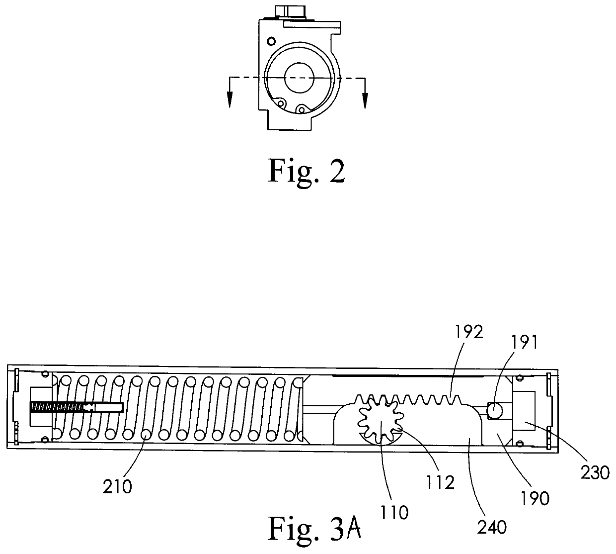
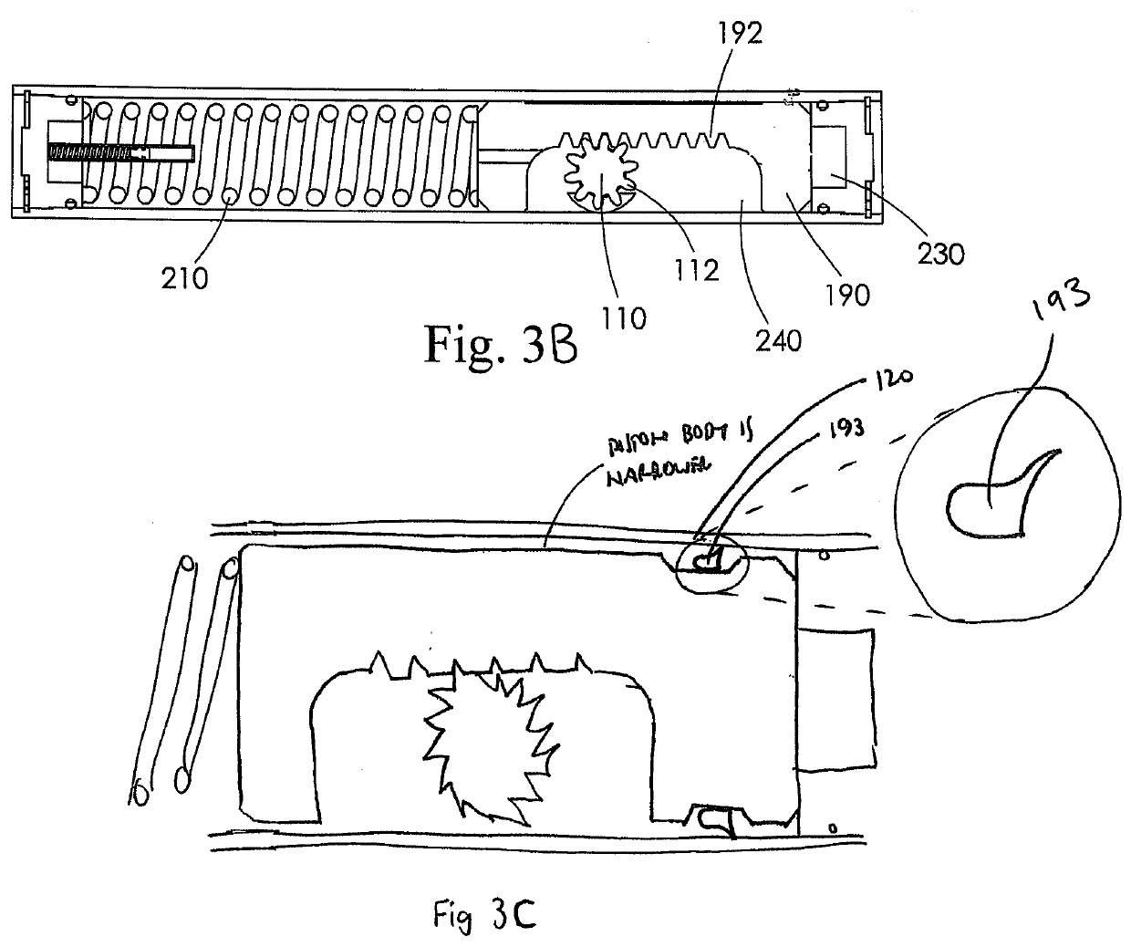
[0044]The incorporation of the overflow chamber or reservoir within the closer allows a space for hydraulic fluid to expand in high temperature situations which controls or tempers the pressure build up and eliminates the hydraulic fluid leakage condition associated with high internal fluid pressures. It may be desirable to incorporate a small one way check valve in the overflow chamber, which will work to reduce or eliminate any back pressure in the closer as the temperature and pressure change during use. This also serves as a means to allow the overflow chamber to be open to ambient air pressure.
[0045]Hydraulic fluid and hydraulic oil are terms that are sometimes used interchangeably, but they are not nec...
PUM
 Abstract
Description
Claims
Application Information