Propulsion system for an aircraft, a nozzle for use with the propulsion system, and a method of manufacturing a propulsion system for an aircraft

a propulsion system and aircraft technology, applied in the field of aircraft, can solve the problems of increasing the magnitude of the sonic boom on the ground, difficult to maintain the smooth contour of the jet plume across a range of aircraft flight conditions or engine power settings, and reducing the disparity

Inactive Publication Date: 2019-11-28
GULFSTREAM AEROSPACE CORP
View PDF0 Cites 2 Cited by
  • Summary
  • Abstract
  • Description
  • Claims
  • Application Information

AI Technical Summary

Benefits of technology

The patent describes a propulsion system for aircraft that includes an engine, a nozzle, a heat source, and pressure sensors. The system uses a pathway through the nozzle with a throat and trailing edge to guide the mass flow. The heat source adds heat to the mass flow as it flows through the nozzle. The system also includes pressure sensors that sense the static and ambient pressure of the mass flow. The controller operates the heat source and the throat / trailing edge to reduce the disparity between the static and ambient pressures. The technical effect is to improve the efficiency and performance of the propulsion system.

Problems solved by technology

Creating a continuously smooth jet plume contour is difficult, and maintaining the smoothness of the contour across a range of aircraft flight conditions or engine power settings is even more challenging.
This expansion and recompression of the free stream gives rise to shocks which will increase the magnitude of the sonic boom on the ground.
When the supersonic freestream changes direction, it will give rise to shocks which lead to an increased magnitude of the sonic boom as perceived on the ground.

Method used


Image

  • Propulsion system for an aircraft, a nozzle for use with the propulsion system, and a method of manufacturing a propulsion system for an aircraft
  • Propulsion system for an aircraft, a nozzle for use with the propulsion system, and a method of manufacturing a propulsion system for an aircraft
  • Propulsion system for an aircraft, a nozzle for use with the propulsion system, and a method of manufacturing a propulsion system for an aircraft

Examples


Embodiment Construction

[0023]The following detailed description is merely exemplary in nature and is not intended to limit the invention or the application and uses of the invention. Furthermore, there is no intention to be bound by any theory presented in the preceding background or the following detailed description.

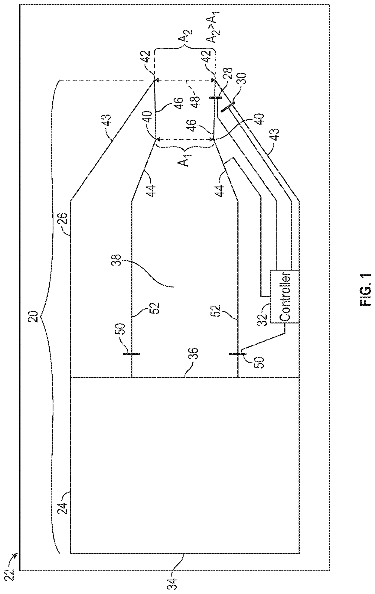
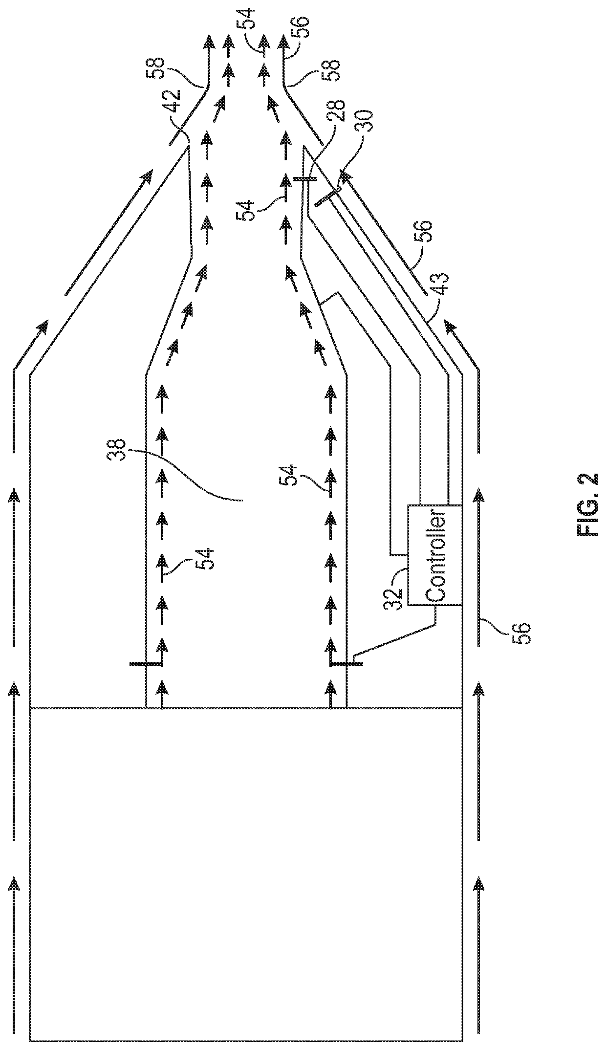
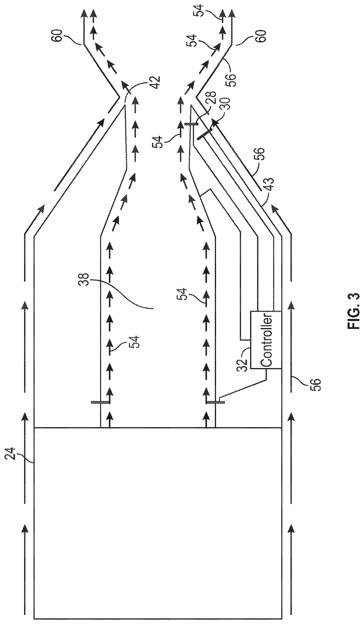
[0024]The first-order influence of temperature on flow density makes it a powerful variable in determining the size and shape of a jet plume. Addressed by this invention, harnessing the effect of temperature through a special fuel spray control system and, in some variants, a variable area nozzle, the geometry of the jet plume can be precisely controlled. For low sonic boom applications, this enables the establishment of a smooth jet plume profile over a broader range of engine operating conditions than would be possible without such a system. The result is a quieter sonic boom signature across a wider operating range.

[0025]An improved propulsion system for use with an aircraft, an improved ...


PUM


Abstract

A propulsion system for an aircraft includes (1) an engine configured to generate a mass flow, (2) a nozzle having a pathway having a throat and a trailing edge, one of the throat and the trailing edge configured to enlarge and contract, (3) a heat source disposed in the nozzle, (4) a first pressure sensor to sense the static pressure of the mass flow at the nozzle exit, (5) a second pressure sensor to sense the ambient pressure proximate the aircraft, and a (6) controller. The controller is coupled with the first and second pressure sensors, the heat source, and the throat or the trailing edge (whichever is configured to enlarge and contract). The controller receives the static and ambient pressures and when there is a disparity, the controller controls at least one of the heat source, the throat, and the trailing edge in a manner that reduces the disparity.

Description

TECHNICAL FIELD[0001]The present invention relates generally to an aircraft, and more particularly relates to a propulsion system for an aircraft that employs reheat to shape an exhaust plume, and a method of manufacturing a propulsion system for an aircraft that employs reheat to shape the exhaust plume.BACKGROUND[0002]An aircraft's sonic boom signature is sensitive to many features of the design, one of which is the shape of the jet plume leaving the engine. The more smoothly a jet plume's contour transitions from the nozzle exit (i.e., the exit plane), the less disruption the plume causes to the local flow field surrounding the nozzle and the less the plume contributes to the loudness of the sonic boom.[0003]Creating a continuously smooth jet plume contour is difficult, and maintaining the smoothness of the contour across a range of aircraft flight conditions or engine power settings is even more challenging. A method for creating a continuously smooth jet plume at the design con...

Claims


Application Information

Patent Timeline
Patent Type & Authority Applications(United States)
IPC IPC(8): F01D17/14B64D33/04F01D17/08F02K1/04
CPCF05D2250/70F02K1/04F05D2260/96F01D17/08B64D2033/0273F01D17/14B64D33/04F05D2220/323B64D2033/0286F05D2220/80F02C1/06F02C9/50F02K1/06F02K1/17F02K3/10
Inventor CONNERS, TIMOTHY R.GAVIN, JOEHOWE, DONALDKNIGHT, MICHAEL
Owner GULFSTREAM AEROSPACE CORP
Why Eureka
Try Eureka