Systems and methods for thermoregulatory sweat testing

a technology of sweat testing and system, applied in the field of diagnostics, can solve the problems of preventing widespread adoption, not being able to evaluate the most distal sites of the body, and sweat dysfunction impairing thermoregulation control in humans

Active Publication Date: 2019-12-05
ANN & ROBERT H LURIE CHILDRENS HOSPITAL OF CHICAGO
View PDF0 Cites 6 Cited by
  • Summary
  • Abstract
  • Description
  • Claims
  • Application Information

AI Technical Summary

Benefits of technology

[0008]One of the objectives of this invention is to provide systems and methods for thermoregulatory sweat testing that improve the standard TST methodology.
[0022]In yet another aspect of the invention, the method for thermoregulatory sweat testing of a living subject having a core body temperature includes using changes in skin temperature caused by forced evaporative cooling to detect body regions which sweat, which eliminates the use of the indicator powder. Skin areas which produce sweat show a rapid drop in temperature with evaporative cooling induced by fanning compared to those areas without sweat. The thermographic measurements reproduce the spatial resolution of powder-based visible light imaging with less mess and discomfort for the patient.

Problems solved by technology

Sweating dysfunction impairs thermoregulatory control in humans.
This method is relatively fast and well-tolerated, but it only tests individual small anatomic regions and is not well suited to evaluating the most distal sites on the body [13].
TST can be central to the identification and management of disorders affecting sudomotor function and small sensory and autonomic nerve fibers, but the cumbersome nature of the standard testing protocol has prevented its widespread adoption.
Therefore, a heretofore unaddressed need exists in the art to address the aforementioned deficiencies and inadequacies.

Method used


Image

  • Systems and methods for thermoregulatory sweat testing
  • Systems and methods for thermoregulatory sweat testing
  • Systems and methods for thermoregulatory sweat testing

Examples


example 1

Novel Methods of Imaging and Analysis for Thermoregulatory Sweat Testing

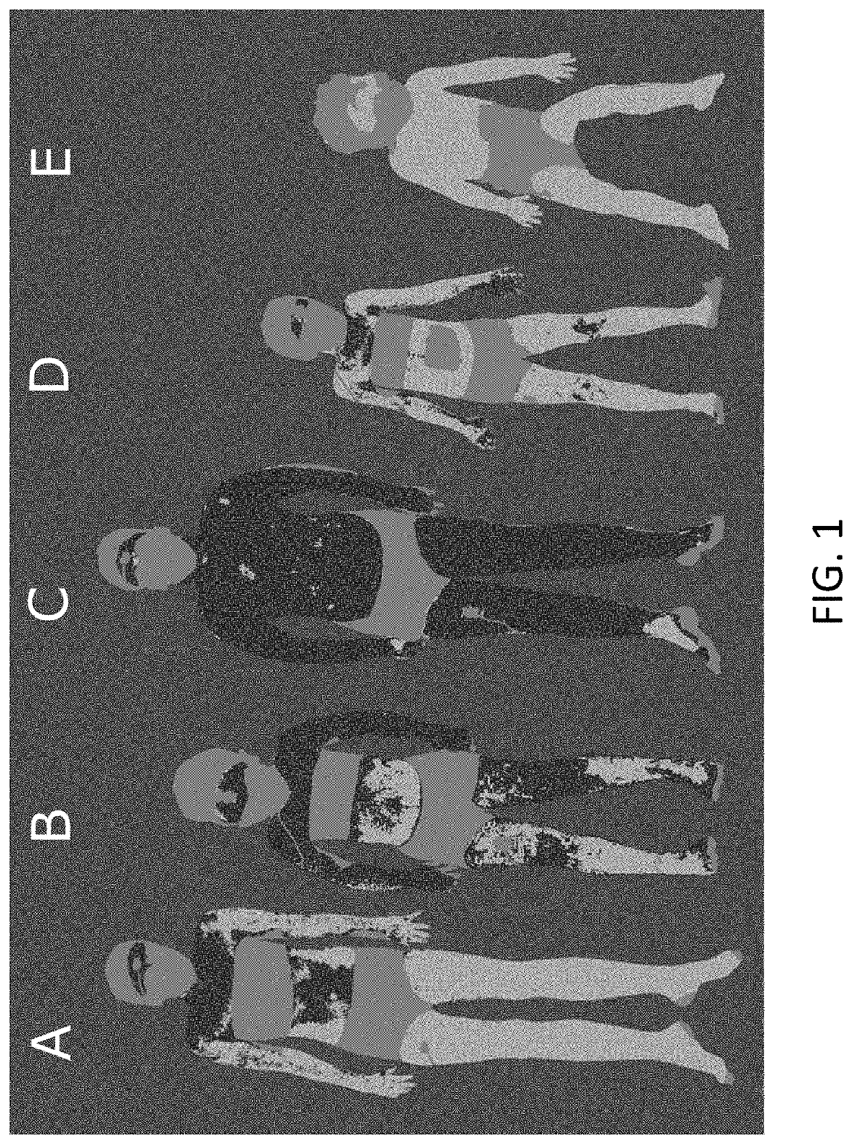
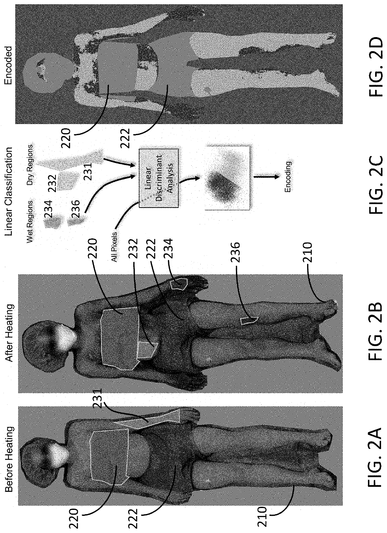
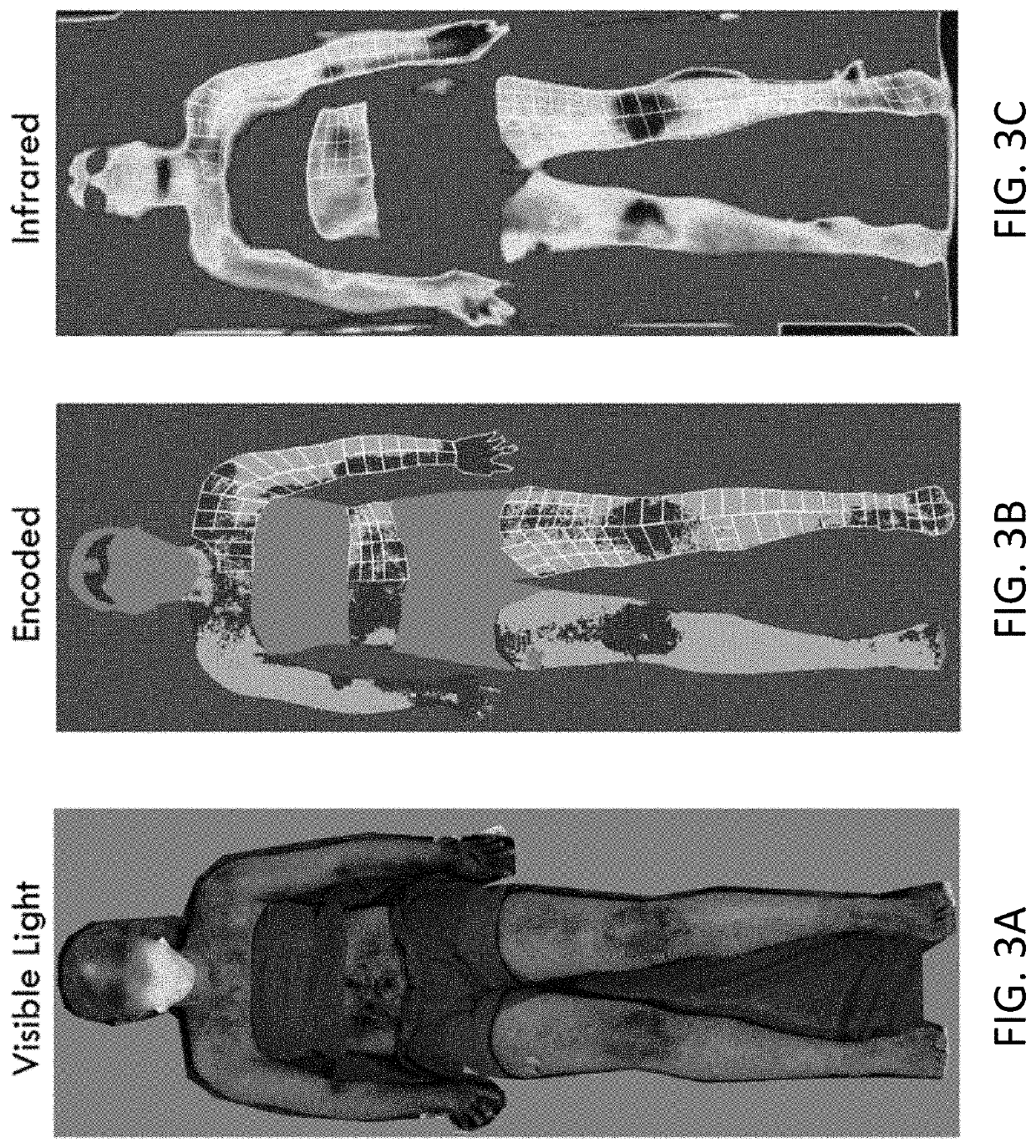
[0103]In this exemplary study, we disclose novel methods that improve the standard TST methodology. The first uses a statistical classification method to partially automate the localization of sweating over the body surface when using the standard indicator powder. The second includes using changes in skin temperature caused by forced evaporative cooling to detect body regions which sweat, an approach that could eliminate the use of the indicator powder. Skin areas which produce sweat show a rapid drop in temperature with evaporative cooling induced by fanning compared to those areas without sweat. The thermographic measurements reproduce the spatial resolution of powder-based visible light imaging with less mess and discomfort for the patient.

[0104]The techniques described here were developed from the Ann & Robert H. Lurie Children's Hospital of Chicago clinical protocol for TST (which is based on the Mayo Clin...

example 2

Infrared Imaging of Evaporative Cooling as a Replacement for Indicator Dye Powder in the Identification of Neurological Disorders

[0128]The objectives of these exemplary studies are, among other things, to replicate previous work establishing that infrared imaging with evaporative cooling (stainless thermoregulatory testing; SST) could identify regions of sweating / non-sweating that well correlated with regions identified with the established method that uses indicator dye powder and visible light imaging; and to replicate these results in tests in which the indicator dye is not used, and to establish that infrared imaging with evaporative cooling alone could identify neuropathy as well as the standard method. For these studies, patients of the neurology service who had done thermoregulatory sweat testing (as part of clinical care, using the standard method) were recruited for repeat studies using the infrared method alone. In addition, several presumptively healthy participants were ...


PUM


Abstract

A system for thermoregulatory sweat testing of a subject includes a chamber for accommodating the subject, the chamber having a heating device for operably elevating the core body temperature of the subject to a target temperature so as to induce sweating over a skin surface of the subject; a cooling device for operably creating forced evaporative cooling of the skin surface of the subject after the core body temperature of the subject is elevated to the target temperature; an imaging device for acquiring images of the subject at different times, each image having imaged pixels, the imaging device including one or more infrared cameras, one or more infrared sensors, or a combination of them; and a controller coupled with the chamber and the imaging device for controlling operations of the chamber and the imaging device and processing the acquired images to determine skin surface sweat distributions of the subject.

Description

CROSS-REFERENCE TO RELATED PATENT APPLICATION[0001]This application claims priority to and the benefit of U.S. provisional patent application Ser. No. 62 / 680,099, filed Jun. 4, 2018, which is incorporated herein in its entirety by reference.[0002]Some references, which may include patents, patent applications and various publications, are cited and discussed in the description of this invention. The citation and / or discussion of such references is provided merely to clarify the description of the present invention and is not an admission that any such reference is “prior art” to the invention described herein. All references cited and discussed in this specification are incorporated herein by reference in their entireties and to the same extent as if each reference was individually incorporated by reference. In terms of notation, hereinafter, “[n]” represents the nth reference cited in the reference list. For example, [2] represents the 2nd reference cited in the reference list, nam...

Claims


Application Information

Patent Timeline
Patent Type & Authority Applications(United States)
IPC IPC(8): A61B5/145A61B5/00
CPCA61B5/0064A61B5/14521A61B5/0077A61B5/01A61B5/4266
Inventor CARROLL, MICHAEL S.WEESE-MAYER, DEBRA E.
Owner ANN & ROBERT H LURIE CHILDRENS HOSPITAL OF CHICAGO
Why Eureka
Try Eureka