Foam waste collecting device and use method thereof

A waste collection and waste technology, applied in cleaning methods and utensils, chemical instruments and methods, solid waste removal, etc., can solve the problems of increased workload of workers, waste of resources, difficult to take out and store, etc. The effect of time utilization, reduced working time, and reduced workload

Inactive Publication Date: 2020-01-17
苏州盛达飞智能科技股份有限公司
View PDF7 Cites 0 Cited by
  • Summary
  • Abstract
  • Description
  • Claims
  • Application Information

AI Technical Summary

Problems solved by technology

[0002] Foam has a series of characteristics such as high elasticity, light weight, fast pressure-sensitive fixation, convenient use, free bending, ultra-thin volume, and reliable performance. Nowadays, foam is used in a wide range of applications, commonly used in furniture, building materials, automotive supplies, electronics, etc. Products and other industries, the continuous expansion of foam demand fields, and the continuous increase in usage will cause a large amount of foam waste to be generated in the process of foam production and use, and a large amount of discarded foam waste cannot be reused. waste of resources, pollution of the environment
[0003] In order to solve the difficulty of recycling waste during foam production and use, the waste and residue cannot be cleaned up in time, causing the workshop or production platform to be messy. At present, the common foam waste recycling has manual cleaning or traditional collection devices, and manual cleaning is mostly used directly. Accumulating or discarding the foam waste not only results in low efficiency of foam waste cleaning, but also fails to clean up the foam waste at the corners of the workshop and in the crevices of the production platform, which increases the workload of workers and wastes unnecessary The foam waste collected by the traditional collection device is not easy to take out and store, and it is difficult to achieve the secondary utilization of the foam waste. It provides an automatic high-efficiency, time-saving and labor-saving, meticulous cleaning, and can granulate the foam waste. Foam waste collection device becomes more and more important

Method used


Image

  • Foam waste collecting device and use method thereof
  • Foam waste collecting device and use method thereof
  • Foam waste collecting device and use method thereof

Examples


Embodiment Construction

[0023] The present invention will be further described in detail below in conjunction with the accompanying drawings, so that those skilled in the art can implement it with reference to the description.

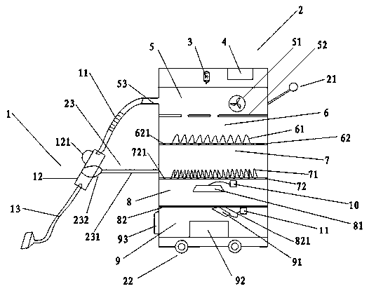
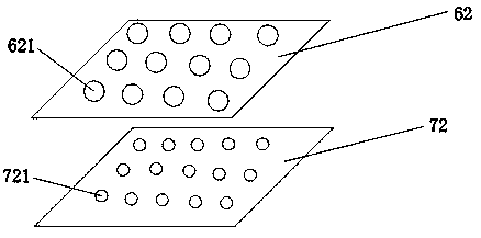
[0024] like Figure 1-3 As shown, this embodiment provides a foam waste collection device, which can automatically and efficiently clean up foam waste and collect foam waste in granules. The foam waste collection device includes: a waste suction assembly 1, a body 2, several Drive motor 3, power supply unit 4, described waste material suction assembly 1 comprises hose 11, plastic hard tube 12, waste material suction head 13, and described fuselage 2 comprises drive layer 5, cutting layer 6, crushing layer 7, hot pressing layer 8. The storage layer 9, the drive 5 is separated from the cutting layer 6 by a baffle plate 52 with a gap, and the cutting layer 6 is separated from the crushing layer 7 by a first screen 62 The crushing layer 7 is separated from the hot-pressed layer ...


PUM


Abstract

A foam waste collecting device comprises a waste suck-in assembly, a machine body, a plurality of driving motors and a power supply device. The waste suck-in assembly comprises a hose, a plastic hardpipe and a waste suck-in head. The machine body comprises a driving layer, a cutting layer, a pulverizing layer, a hot pressing layer and a storing layer. A communicating pipe is welded to the outer surface of the driving layer. A support is welded to the surface of the machine body. The support comprises a transverse rod and a support head. The plastic hard pipe is connected with the support headin a buckled mode. One side of the plastic hard pipe is connected with the waste suck-in head in a thread rotating mode. The other side of the plastic hard pipe is connected with the hose in a buckled mode. The side, close to the driving layer, of the hose is connected with the communicating pipe in a clamped mode. By means of the foam waste collecting device, the workloads and working hours of workers are reduced, foam waste is efficiently and fine cleaned up, and the foam waste is granulated to be stored.

Description

technical field [0001] The invention relates to a foam waste collecting device and a method for using the same, belonging to the technical field of foam waste collection. Background technique [0002] Foam has a series of characteristics such as high elasticity, light weight, fast pressure-sensitive fixation, convenient use, free bending, ultra-thin volume, and reliable performance. Nowadays, foam is used in a wide range of applications, commonly used in furniture, building materials, automotive supplies, electronics, etc. Products and other industries, the continuous expansion of foam demand fields, and the continuous increase in usage will cause a large amount of foam waste to be generated in the process of foam production and use, and a large amount of discarded foam waste cannot be reused. Cause waste of resources and pollution of the environment. [0003] In order to solve the difficulty of recycling waste during foam production and use, the waste and residue cannot be...

Claims


Application Information

Patent Timeline
Patent Type & Authority Applications(China)
IPC IPC(8): B08B15/00B08B15/04B09B3/00B09B5/00B02C18/00B02C18/10B02C18/24B02C23/16B02C23/14B26D1/10B30B9/30B30B15/34
CPCB08B15/00B08B15/04B09B3/00B09B5/00B02C18/0084B02C18/10B02C18/24B02C23/16B02C23/14B26D1/10B30B9/30B30B9/305B30B15/34B02C2023/165B02C2201/06
Inventor 林志武高凌文杨滨
Owner 苏州盛达飞智能科技股份有限公司
Why Eureka
Try Eureka