Biopsy device having a linear motor drive

a technology of biopsy device and linear drive, which is applied in the field of biopsy device, can solve problems such as significant noise, and achieve the effect of significant noise reduction and reduced or eliminated component impa

Active Publication Date: 2019-12-05
CR BARD INC
View PDF0 Cites 1 Cited by
  • Summary
  • Abstract
  • Description
  • Claims
  • Application Information

AI Technical Summary

Benefits of technology

[0008]An advantage of the present invention is that by using one or more linear motors to replace the firing springs associated with propelling the cutting cannula or the stylet or both forward, component impact is reduced or eliminated, yielding significant noise reduction.
[0009]Another advantage is that by using one or more linear motors to control linear displacement of the cutting cannula and stylet, virtually any combination of linear movements of the cutting cannula and the stylet, alone or in combination, is possible.
[0010]Yet another advantage is that by using one or more linear motors to move the cutting cannula relative to the stylet, the exposed extent of the sample notch of the stylet can be precisely controlled, so as to provide a continuous range of possible sample size openings at the sample notch.

Problems solved by technology

Particularly during a firing operation, the spring-loaded components move forward to impact a mechanical stop, resulting in significant noise.

Method used


Image

  • Biopsy device having a linear motor drive
  • Biopsy device having a linear motor drive
  • Biopsy device having a linear motor drive

Examples


Embodiment Construction

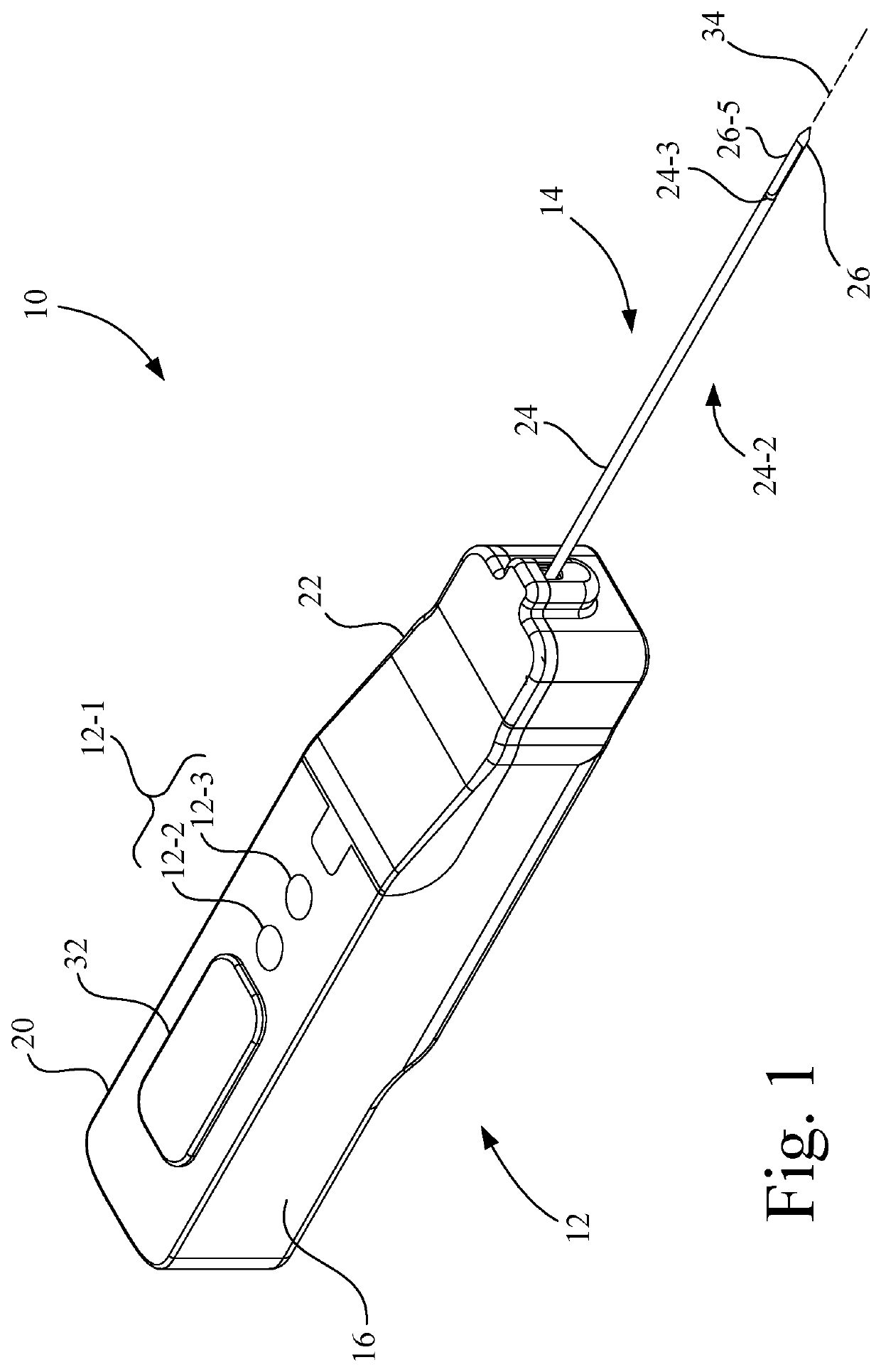
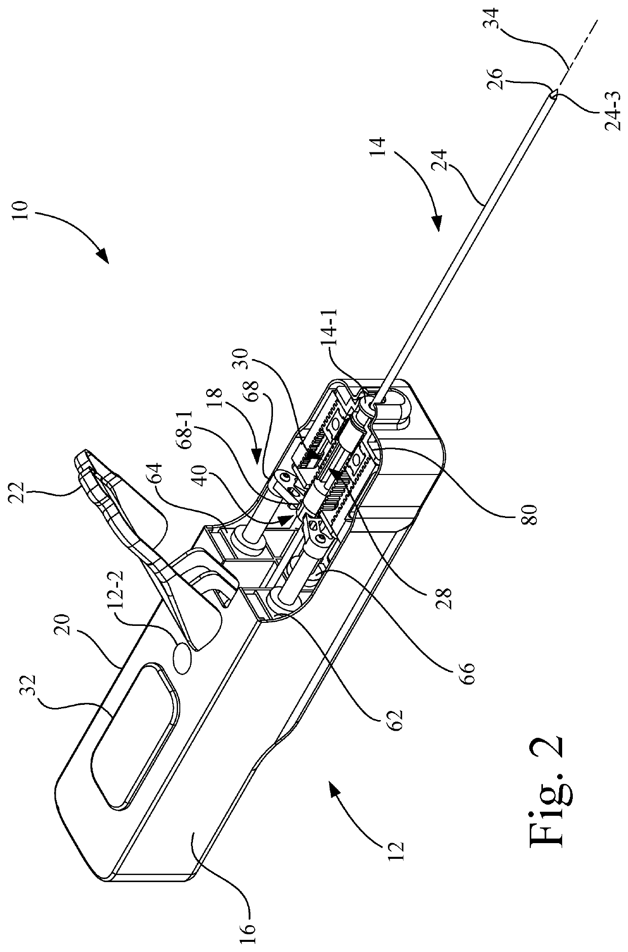
[0033]Referring now to the drawings, and more particularly to FIGS. 1 and 2, there is shown a biopsy device 10 which generally includes a driver assembly 12 and a disposable biopsy needle assembly 14. In the present embodiment, driver assembly 12 may be reusable on multiple patients, whereas disposable biopsy needle assembly 14 is used only on a single patient. As used herein, the term “disposable” refers to a device that is intended for use with one patient only, and is discarded after use.

[0034]As shown in FIG. 1, driver assembly 12 includes a user interface circuit 12-1. User interface circuit 12-1 is configured to receive a user input and generate a corresponding user output signal that is supplied to controller components of driver assembly 12. In the present embodiment, user interface circuit 12-1 may be a simple touch pad having a plurality of control buttons, individually identified as prime-pierce button 12-2 and sample button 12-3. Alternatively, it is contemplated that us...


PUM


Abstract

A biopsy device includes a first cannula driver connected to a first cannula and a second cannula driver connected to a second cannula. The first cannula driver has a first rack member and a flange. The second cannula driver has a second rack member. A drive assembly has a linear motor drive, a transmission assembly, a switching motor drive, and an electrical controller circuit. The electrical controller circuit is configured to execute program instructions to selectively operate the linear motor drive and the switching motor drive. The transmission assembly has a gear assembly drivably coupled to the switching motor drive and configured to releasably engage at least one of the first rack member of the first cannula driver and the second rack member of the second cannula driver. A coupler member is connected to the linear motor drive, and is configured to engage the flange of the first cannula driver.

Description

CROSS-REFERENCE TO RELATED APPLICATIONS[0001]This application claims priority to U.S. provisional patent application Ser. No. 62 / 434,704, entitled “BIOPSY DEVICE HAVING A LINEAR MOTOR DRIVE” filed Dec. 15, 2016, which is incorporated herein by reference.TECHNICAL FIELD[0002]The present invention relates to biopsy devices, and, more particularly, to a biopsy device having a linear motor drive.BACKGROUND ART[0003]A biopsy may be performed on a patient to help in determining whether the cells in a biopsied region are cancerous. One type of biopsy device for performing a biopsy includes a hand-held driver assembly having an electromechanical driver that is attachable to a disposable biopsy probe assembly. The disposable biopsy probe assembly typically includes a stylet having a sample notch, and a cutting cannula coaxial with the stylet and movable relative to the stylet to selectively cover and uncover the sample notch. During a piercing operation, the cutting cannula and the stylet ar...

Claims


Application Information

Patent Timeline
Patent Type & Authority Applications(United States)
IPC IPC(8): A61B10/02
CPCA61B2010/0208A61B10/0275
Inventor VAN LIERE, CHAD
Owner CR BARD INC
Why Eureka
Try Eureka