Drill Bit Having a Spiral-Tube-Shaped Drill Shaft and Method for Producing a Spiral-Tube-Shaped Drill Shaft for a Drill Bit

Inactive Publication Date: 2019-12-05
HILTI AG
View PDF13 Cites 1 Cited by
  • Summary
  • Abstract
  • Description
  • Claims
  • Application Information

AI Technical Summary

Benefits of technology

[0025]In a particularly preferred variant of the method, the seam material has a higher tensile strength, a higher wear resistance or a higher tensile strength and wear resistance than the N, N≥1 strip materials. The use of seam materials having a higher tensile strength, higher wear resistance or higher tensile strength and wear resistance than the strip materials can influence the properties of the spiral-shaped connection weld, so that the guidance of the drill shaft over the spiral-shaped connection weld is ensured as far as possible throughout the life of the drill shaft.
[0026]In an alternative particularly preferred variant of the method, a first seam material and a second seam material are used when joining the abutting strip edges of the N, N≥1 strip mat

Problems solved by technology

The lack of guidance of the drill shaft can lead to undesired movements of the drill bit during drilling, which can impair the quality of the borehole.
In addition, elastic deformations of the drill shaft can occur due to the force exerted by the drilled core or the borehole on the drill shaft.
The disadvantage is that the drill shaft has a large contact surface to the drilled core on the inside and a large contact surface to the borehole on the outside.
The large contact surfaces on the inside and outside of the drill sha

Method used


Image

  • Drill Bit Having a Spiral-Tube-Shaped Drill Shaft and Method for Producing a Spiral-Tube-Shaped Drill Shaft for a Drill Bit
  • Drill Bit Having a Spiral-Tube-Shaped Drill Shaft and Method for Producing a Spiral-Tube-Shaped Drill Shaft for a Drill Bit
  • Drill Bit Having a Spiral-Tube-Shaped Drill Shaft and Method for Producing a Spiral-Tube-Shaped Drill Shaft for a Drill Bit

Examples


Example

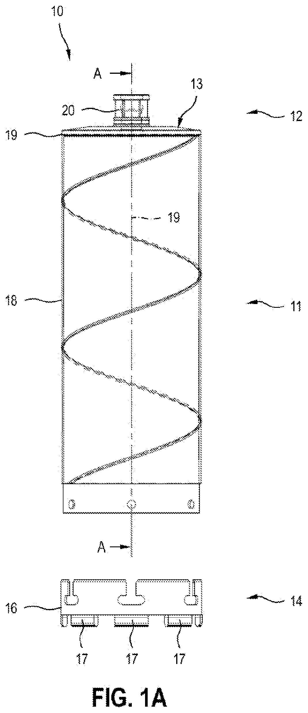
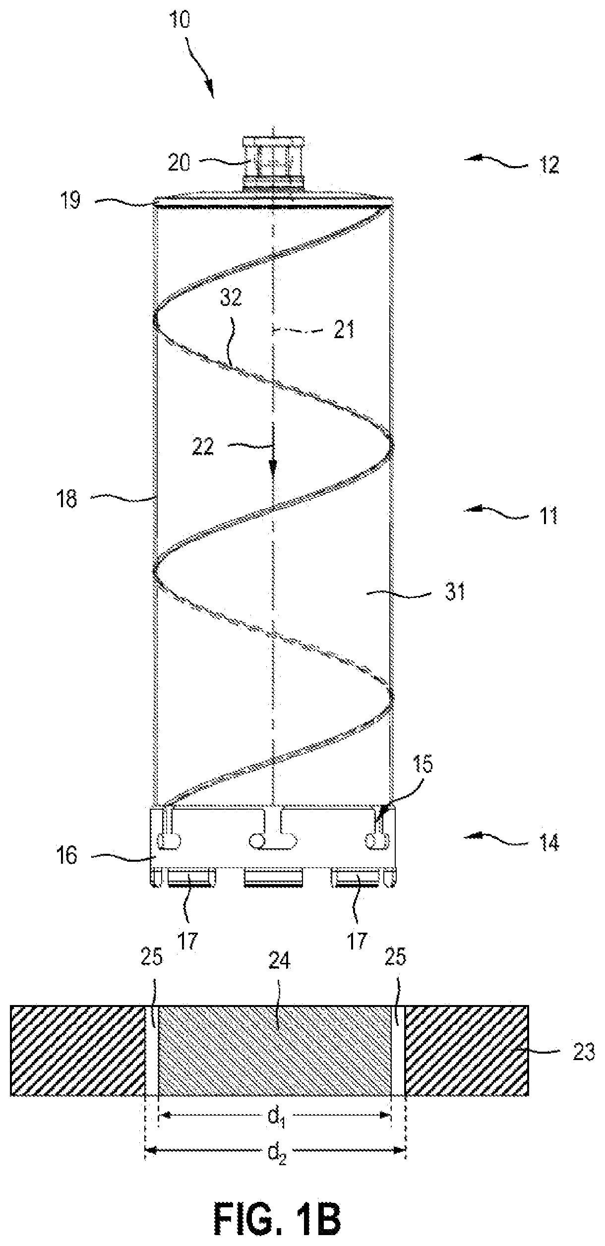
[0034]FIGS. 1A, B show a first embodiment of an inventive drill bit 10, hereinafter referred to as the first drill bit 10. The first drill bit 10 comprises a drill shaft portion 11, a receiving portion 12 and a connecting device 13 which permanently connects the drill shaft portion 11 to the receiving portion 12. The first drill bit 10 can be connected to a separate cutting portion 14 via another detachable connecting device 15. FIG. 1A shows the first drill bit 10 and the cutting portion 14 in the unconnected state and FIG. 1B the first drill bit 10 and the cutting portion 14 in the connected state.

[0035]The cutting portion 11 comprises a ring portion 16 and several cutting segments 17 connected to the ring portion 16. The cutting segments 17 are arranged in a ring shape and form a cutting ring with intermediate spaces. The cutting portion 14 can also have a single cutting segment designed as a closed cutting ring instead of several cutting segments 17. The cutting segments 17 are ...

Example

[0040]FIG. 3 shows a second embodiment of an inventive drill bit 40, hereinafter referred to as the second drill bit 40. The second drill bit 40 comprises a drill shaft portion 41, a receiving portion 42, and a connecting device 43, which permanently connects the drill shaft portion 41 to the receiving portion 42.

[0041]Drill shaft portion 41 includes a spiral-tube-shaped drill shaft 44 and multiple cutting segments 45 that are welded, soldered, bonded or fastened to the drill shaft 44 in any other suitable manner. The receiving portion 42 comprises a cover 46 and an insertion end 47, through which the third drill bit 40 is fastened in a tool holder of a core drill. In drilling operation, the second bit 40 is driven by the core drill about a drilling axis 48 and moved in a drilling direction 49 parallel to the drilling axis 48 into the workpiece 23 to be machined.

[0042]The second drill bit 40 has several cutting segments 45, which are permanently attached to the drill shaft 44. The s...

Example

[0051]FIG. 5 shows a third embodiment of an inventive drill bit 60, hereinafter referred to as the third drill bit 60. The third drill bit 60 comprises a drill shaft portion 61, a receiving portion 62 and a connecting device 63, which connects the drill shaft portion 61 permanently with the receiving portion 62.

[0052]Drill shaft portion 61 includes a spiral-tube-shaped drill shaft 64 and multiple cutting segments 65 welded, soldered, bonded or otherwise fastened to the drill shaft 64 in another suitable manner. The receiving portion 62 includes a cover 66 and an insertion end 67, over which the third drill bit 60 is fastened in a tool holder of a core drill. In drilling operation, the third drill bit 60 is driven by the core drill about a drilling axis 68 and moved in a drilling direction 69 parallel to the drilling axis 68 into the workpiece 23 to be machined.

[0053]The third drill bit 60 has several cutting segments 65, which are attached to the drill shaft 64 in a permanent manner...


PUM

PropertyMeasurementUnit
Thicknessaaaaaaaaaa
Diameteraaaaaaaaaa
Wear resistanceaaaaaaaaaa

Abstract

A drill bit for creating a borehole includes a drill shaft portion which has a tubular drill shaft, a receiving portion which has a cover and an insertion end, and a connecting device which connects the drill shaft portion and the receiving portion together releasably or non-releasably. The tubular drill shaft is configured as a welded spiral tube.

Description

CROSS REFERENCE TO RELATED APPLICATIONS[0001]This application claims the priority of International Application No. PCT / EP2017 / 080663, filed Nov. 28, 2017, and European Patent Document No. 16206533.8, filed Dec. 23, 2016, the disclosures of which are expressly incorporated by reference herein.BACKGROUND AND SUMMARY OF THE INVENTION[0002]The present invention relates to a drill bit with a spiral-tube-shaped drill shaft and a method for producing a spiral-tube-shaped drill shaft for such a drill bit.[0003]Drill bits consist of a tube-shaped drill shaft, a cover that closes the tube-shaped drill shaft, and an insertion end above which the drill bit is fastened in the tool holder of a core drill. The cover and insertion end are parts of a receiving portion and the drill shaft is part of a drill shaft portion. The drill shaft portion and the receiving portion are detachably or permanently connected by means of a connecting device.[0004]In the case of known drill bits, a distinction is mad...

Claims


Application Information

Patent Timeline
IPC IPC(8): B23B51/04E21B10/62
CPCB23B51/042B23B2240/16E21B10/62E21B17/046B23B2251/408B23B2250/12B23P15/28B23B51/04
Inventor SCHROEDER, FLORIANWEBER, CHRISTOPHSCHNEIDER, ROLAND
Owner HILTI AG
Why Eureka
Try Eureka