
Magnifying display screen device

a display screen and display screen technology, applied in the direction of optical elements, instruments, substation equipment, etc., can solve the problems of limited operating distance, unrealistic difficulties, easy fatigue of eyes, etc., and achieve the effect of reducing eye burden, convenient use, and easy obtaining the optimal viewing angl

Inactive Publication Date: 2019-12-05
E LEAD ELECTRONICS
View PDF1 Cites 7 Cited by
  • Summary
  • Abstract
  • Description
  • Claims
  • Application Information

AI Technical Summary

Benefits of technology

The present invention is a magnifying display screen device that provides an optimized projection light path for mobile phones, computers, or TVs. The device allows users to easily watch an ideal magnified image without having to adjust the distance and projection angle of the display module, reflective module, and magnifying module. The device is easy to use and may effectively solve the drawbacks of conventional devices. Additionally, the device can magnify objects several times and image them far longer than the actual object distance. This further reduces the burden on the eyes and provides a more comfortable viewing experience.

Problems solved by technology

Actually, it is just limited by the operating distance and the size of text and pictures on screen or on books that could not see clearly if it is too far, so the recommendation exists.
Do not let children play smart phone is deprived of their leisure, and there are unrealistic difficulties.
However, if the visual distance becomes longer, eye recognition ability may decrease, so it is easy to make eyes tired unless fonts and images are enlarged.
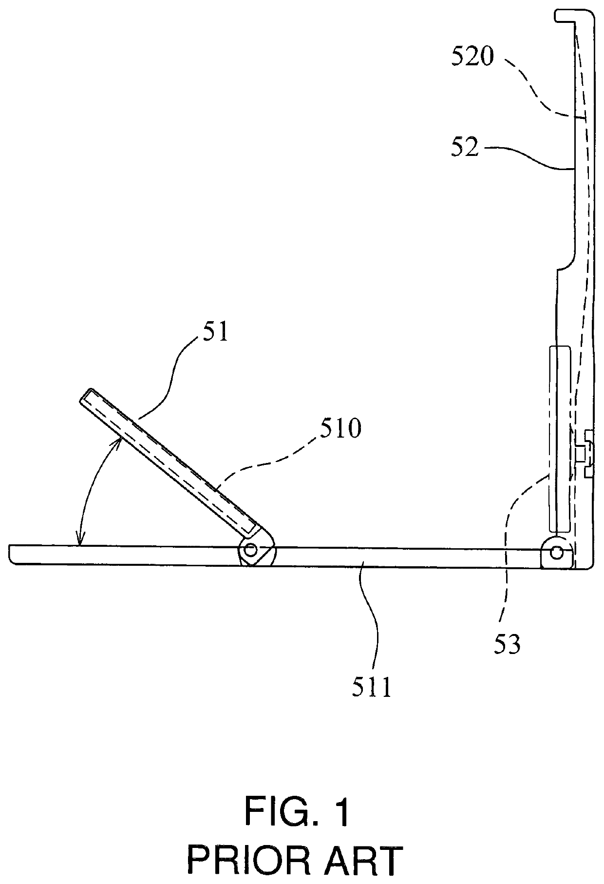
Although the cited reference may provide to magnify and display image content of mobile phones for users to conveniently watch the screen content, users have to manually adjust the angle and the distance of the projection mirror 51 and the magnifier 52 when using it, such an adjustment operation is troublesome and time-consuming for users, it is inconvenient because the optimized projection light path cannot be obtained immediately for users to watch.
Moreover, the cited reference is limited to magnify a mobile phone screen, it does not provide for a computer or a TV screen to magnify, so its range of use is very limited.

Method used


Image

  • Magnifying display screen device
  • Magnifying display screen device
  • Magnifying display screen device

Examples


Embodiment Construction

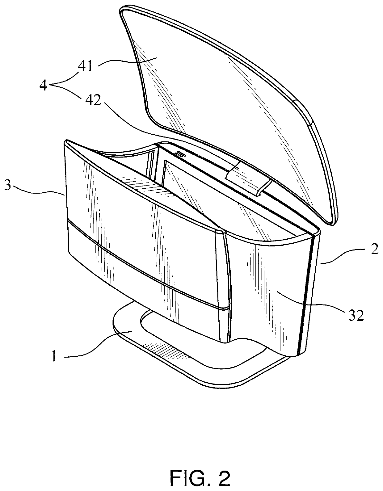
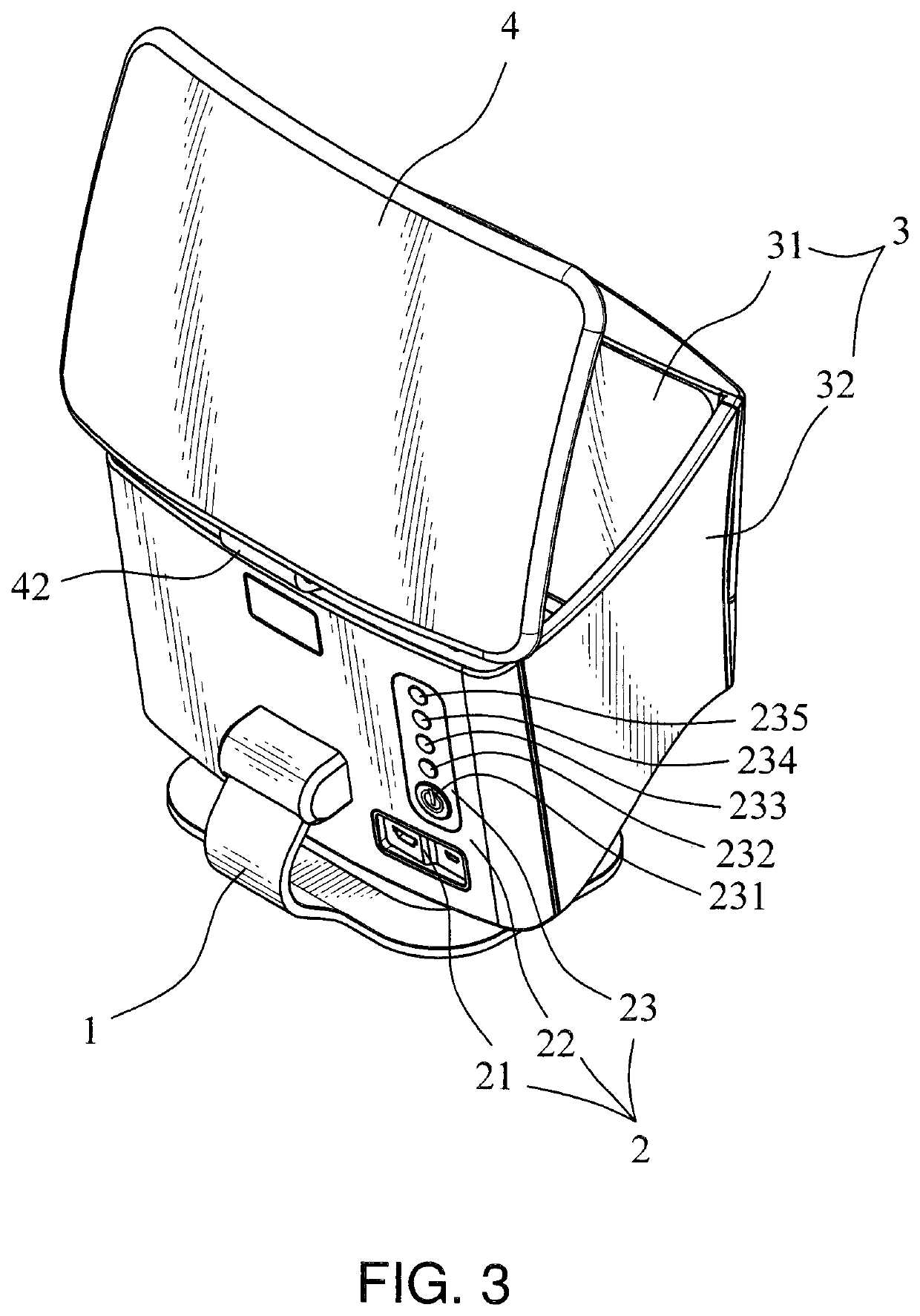
[0029]Please refer to FIG. 2 to FIG. 4, the magnifying display screen device A of the present invention includes:

[0030]a stand 1, a shaft 11 is set on it;

[0031]a display module 2, its one side is pivoted on the shaft 11, the display module 2 is provided to display an image;

[0032]a reflective module 3, which includes a reflective sheet 31 and a light shield 32, the reflective sheet 31 is a convex mirror, the reflective sheet 31 is provided to receive the image displayed by the display module 2 and reflect a reflection image, the light shield 32 is fixed on two sides of the display module 2 and a box body is formed;

[0033]a magnifying module 4, which includes a magnifying sheet 41 and a bracket 42, the bracket 42 is fixed to the top of the display module 2, the magnifying sheet 41 is a concave mirror, principle of virtual imaging is imaging by using a concave mirror, the imaging formula of a concave mirror is: 1 / p+1 / q=1 / f, wherein f: focal distance, q: object distance, p: image distanc...


PUM


Abstract

The present invention relates to a magnifying display screen device, which includes a stand, a display module, a reflective module and a magnifying module, objects could be magnified several times and imaged far longer than several times of the object distance according to the principle of virtual imaging of concave mirrors, and a screen image of a mobile phone, a computer, a video player, a USB flash drive or a SD memory card can be magnified by a connection with the mobile phone, the computer the video player, the USB flash drive or the SD memory card, to thereby provide the optimized projection light path, so that users could watch an ideal magnified image to effectively reduce the burden on eyes.

Description

BACKGROUND OF THE INVENTIONa) Field of the Invention[0001]The invention relates to a magnifying display screen device and, more particularly, to a magnifying display screen device for providing an optimized projection light path, and a screen image of a mobile phone, a computer or a TV can be magnified by a connection with the mobile phone, the computer or the TV, so that users could watch an ideal magnified image to thereby effectively reduce the burden on eyes.b) Description of Prior Art[0002]Medicine has proven that look near for a long time is the main cause of myopia except 5% genetic factors. Let's recall activities in daily life that looking near for a long time. Watching TV may usually be thought of, but distance between users and TV is above two or three meters, it is not really looking near. As for eating or dressing, although it is looking near, it is not for a long time. The main activities that looking near for a long time is reading books and writing, looking at mobile...

Claims


Application Information

Patent Timeline
Patent Type & Authority Applications(United States)
IPC IPC(8): G02B25/00H04M1/02
CPCG02B25/002H04M1/027G02B5/10G02B27/18G02B27/04G03B21/28G03B21/10G03B21/145H04M1/72409
Inventor CHEN, STEPHEN
Owner E LEAD ELECTRONICS
Learn More