Fluid circulation pipe for motor vehicle, method for manufacturing same and use thereof as motor vehicle engine coolant hose

Active Publication Date: 2019-12-12
TRISTONE FLOWTECH SOLUTIONS TFS
View PDF0 Cites 0 Cited by
  • Summary
  • Abstract
  • Description
  • Claims
  • Application Information

AI Technical Summary

Benefits of technology

The invention aims to reduce the weight of cooling pipes to make vehicles lighter, use a fewer number of polymer materials to simplify manufacturing and reduce costs, and make the fluid flow pipe easier to recycle.

Problems solved by technology

The main constraints on such pipes lies with withstanding high temperatures and pressure while the engine is in operation, and their ability to withstand attack from the liquid being transported.
The main drawbacks of those types of pipe incorporating at least one reinforcing layer are associated with their weight and their bulk (in particular because of their thickness).
In addition, such multilayer structures have materials that are difficult to separate for recycling purposes.

Method used


Image

  • Fluid circulation pipe for motor vehicle, method for manufacturing same and use thereof as motor vehicle engine coolant hose

Examples


Embodiment Construction

[0011]To this end, the present invention provides a motor vehicle cooling fluid flow pipe, such as an engine cooling fluid pipe, characterized in that the wall of the pipe is constituted by a single layer made of a polymer material comprising a mixture of at least two polymer materials of different natures, one of which, referred to as a first material, being a polyolefin, and the other of which, referred to as a second material, being a thermoplastic polymer elastomer (TPE). Advantageously, the wall of the pipe is constituted by a single layer made of a polymer material constituted exclusively of the mixture of said first material and of said second material.

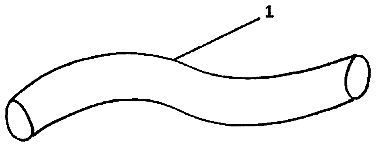
[0012]The term “pipe” is used below throughout the present text to designate any tube, tubing, hose, piping, and thus in particular engine cooling fluid pipes.

[0013]Surprisingly, the inventors have been able to make a pipe having a single-layer wall that satisfies the criteria set out in the introduction by means of a mixture o...


PUM

PropertyMeasurementUnit
Temperatureaaaaaaaaaa

Abstract

A motor vehicle cooling fluid flow pipe, such as an engine cooling fluid pipe, characterized in that the wall of the pipe is constituted by a single layer made of a polymer material comprising a mixture of at least two polymer materials of different natures, one of which, referred to as a first material, being a polyolefin, and the other of which, referred to as a second material, being a thermoplastic polymer elastomer (TPE).The method of manufacturing this pipe comprises an operation of mixing at least the polyolefin and the thermoplastic polymer elastomer (TPE), a step of extruding said mixture in a screw extruder followed by a step of forming the pipe, the operation of mixing the polyolefin and the thermoplastic polymer elastomer (TPE) being performed upstream from the extruder or at its inlet.

Description

FIELD OF THE INVENTION[0001]The present invention relates to the field of fluid flow pipes. More particularly, the invention relates to fluid flow pipes for motor vehicles, such as an engine cooling fluid pipe, and also to a method of manufacturing such a pipe.PRIOR ART[0002]Fluid flow pipes, such as the pipes used in the automobile industry, are used in particular for conveying a cooling fluid, such as a mixture of water and ethylene glycol, in the cooling circuit of the engine. The main constraints on such pipes lies with withstanding high temperatures and pressure while the engine is in operation, and their ability to withstand attack from the liquid being transported. In particular, the use of polyurethane is avoided since it is incompatible with contact with fluids that contain a glycol.[0003]At present, these fluid flow pipes, such as pipes for engine cooling liquid, are generally made as one or more layers of polymer elastomer material (such as rubber) reinforced by a knit or...

Claims


Application Information

Patent Timeline
IPC IPC(8): F16L11/12C08L23/12C08L23/02C08L23/06
CPCC08L2207/04C08L2207/062C08L23/025F16L11/12C08L23/06C08L2203/18C08L2205/025C08L23/12C08L2205/00C08L53/02
Inventor SAINT-LARY, DOMINIQUELE BRIQUER, FRANCOIS
Owner TRISTONE FLOWTECH SOLUTIONS TFS
Why Eureka
Try Eureka