Bracket connection structure and bracket

a connection structure and bracket technology, applied in the direction of coupling device connection, furniture parts, movable shelf cabinets, etc., can solve the problems of cumbersome assembling and disassembling of the bracket, the connection mode may not realize the detachable function, and the inconvenient transportation, so as to ensure the connection strength and connection stability, and the structure is simple. , the effect of convenient assembling and disassembly

Active Publication Date: 2019-12-19
SHANGHAI EYEMOVE IMAGE PRINTING CO LTD
View PDF3 Cites 0 Cited by
  • Summary
  • Abstract
  • Description
  • Claims
  • Application Information

AI Technical Summary

Benefits of technology

The present invention provides a bracket connection structure and a bracket adopting the connection structure. The connection structure allows for quick and easy connection, and can be used with existing movable pieces. The bracket connection structure features matching connection of convex clasps and jacks, ensuring connection strength and stability. Additionally, the bracket has an electric connection structure, simplifying the cabling process and providing intelligence. The bracket's connection hole structures can also serve as structures for connected fixed pieces, simplifying the structure and allowing for functional diversification.

Problems solved by technology

1. The supporting pieces and the fixed pieces are directly welded together, but this connection mode may not realize a detachable function and is inconvenient for transportation.
2. The supporting pieces and the fixed pieces are connected together through connection pieces such as screws, but this connection mode makes assembling and disassembling of the bracket cumbersome.
3. Fastener holes are formed in the supporting pieces, and fasteners are arranged on the fixed pieces, and fixed connection between the fixed pieces and the fastener holes is realized by fastening the fasteners into the fastener holes, but in this connection mode, the fasteners need to be knocked into the fastener holes, and the fastener holes may not be in matching connection with the movable pieces provided with hooks.
4. Hanging holes are formed in the supporting pieces, and hooks are arranged on the fixed pieces and the movable pieces. The fixed pieces are further fixedly connected with the supporting pieces by hanging the hooks in the hanging holes of the supporting pieces and by assembling connection pieces such as screws, and the movable pieces are directly hung in the hanging holes through the hooks, as shown in FIGS. 1 to 2. In this connection mode, although the hanging holes in the supporting pieces may be simultaneously applicable to connecting the fixed pieces and the movable pieces, the connection of the fixed pieces still needs the screws and other parts for further fixing, resulting in cumbersome assembling and disassembling of the bracket.
5. For an electronic shelf type bracket, various types of electrical equipment need to be disposed and the electrical equipment need to be connected with a power supply for work.
Directly leading a power line to a corresponding shelf in the prior art to charge these equipment inevitably causes chaotic cabling on the shelf and in a warehouse, which is inconvenient for management and unfavorable for fetching and placement of objects on the shelf.

Method used


Image

  • Bracket connection structure and bracket
  • Bracket connection structure and bracket
  • Bracket connection structure and bracket

Examples


embodiment 1

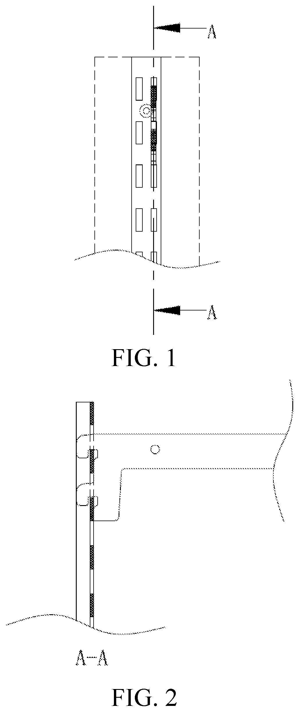
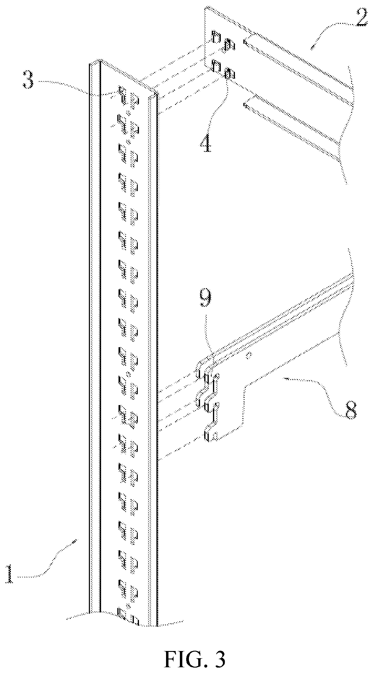
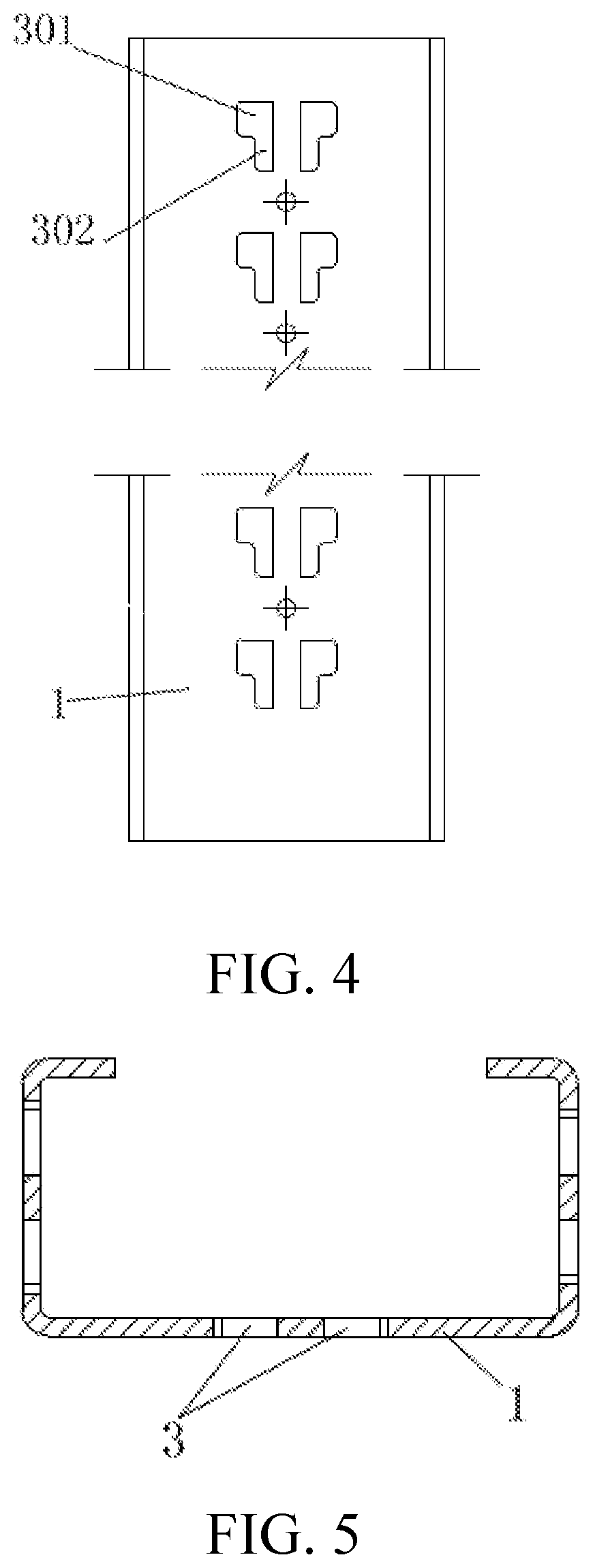
[0072]Referring to FIGS. 3 to 11, the present invention provides a bracket connection structure, used for connecting a supporting piece 1 with a fixed piece 2 of a bracket. The bracket connection structure includes at least one group of connection hole structures arranged on the supporting piece 1 and at least one group of convex structures arranged on the fixed piece 2. The connection hole structures at least include two symmetrically disposed jacks 3, and the convex structures include two symmetrically disposed convex clasps 4. The jacks 3 include insertion portions 301 and clamping portions 302 which are communicated with each other. A clearance of the clamping portions 302 is smaller than that of the insertion portions 301 so as to realize matching. The convex clasps 4 are inserted into the insertion portions 301 and move to be clamped into the clamping portions 302.

[0073]According to the connection structure provided by the present invention, the convex clasps are inserted into...

embodiment 2

[0082]As jacks or convex clasps are inconvenient to be disposed on certain brackets, such as on certain furniture, the present invention facilitates the setting of a connection structure by disposing the jacks or convex clasps onto connection pieces and detachably mounting the connection pieces onto a supporting piece and a fixed piece.

[0083]Specifically, a bracket connection structure includes a first connection piece detachably mounted on the supporting piece 1. At least one group of connection hole structures are arranged on the first connection piece. At least one group of convex structures are arranged on the fixed piece. The connection hole structures include two symmetrically disposed jacks, and the convex structures include two symmetrically disposed convex clasps. The jacks include insertion portions and clamping portions which are communicated with each other. A clearance of the clamping portions is smaller than that of the insertion portions. The convex clasps are inserte...

embodiment 3

[0091]Referring to FIGS. 16 to 20, the present invention provides a bracket connection structure, used for connecting a supporting piece 1 with a fixed piece 2 of a bracket. The bracket connection structure includes at least one group of connection hole structures arranged on the supporting piece 1 and at least one group of convex structures arranged on the fixed piece 2. The connection hole structures at least include upper and lower jacks 3 facing the same direction, and the convex structures include upper and lower convex clasps 4 facing the same direction. The jacks 3 include insertion portions 301 and clamping portions 302 which are communicated with each other. A clearance of the clamping portions 302 is smaller than that of the insertion portions 301. The convex clasps 4 are inserted into the insertion portions 301 and move to be clamped into the clamping portions 302.

[0092]According to the connection structure provided by the present invention, the convex clasps are inserted...


PUM


Abstract

The present invention discloses a bracket connection structure, used for connecting a supporting piece with a fixed piece of a bracket. The bracket connection structure includes at least one group of connection hole structures arranged on the supporting piece and at least one group of convex structures arranged on the fixed piece. Jacks include insertion portions and clamping portions which are communicated with each other. A clearance of the clamping portions is smaller than that of the insertion portions. Convex clasps are inserted into the insertion portions and move to be clamped into the clamping portions. Further, corresponding positions on the back surfaces of the jacks are all provided with electric connection sheets connected to an external power supply. The present invention further provides a bracket, including a supporting piece and a fixed piece. The supporting piece and the fixed piece are connected through the bracket connection structure.

Description

BACKGROUNDTechnical Field[0001]The present invention relates to the technical field of design of connection structures, and particularly relates to a bracket connection structure and a bracket.Related Art[0002]Equipment, such as furniture, goods shelves, showing stands and commodity shelves, in the existing life generally includes detachable brackets. The bracket is generally formed by connecting a plurality of supporting pieces, fixed pieces and movable pieces.[0003]Direct connection modes between the supporting pieces and the fixed pieces in the prior art generally comprises the following several modes:[0004]1. The supporting pieces and the fixed pieces are directly welded together, but this connection mode may not realize a detachable function and is inconvenient for transportation.[0005]2. The supporting pieces and the fixed pieces are connected together through connection pieces such as screws, but this connection mode makes assembling and disassembling of the bracket cumbersom...

Claims


Application Information

Patent Timeline
IPC IPC(8): A47B57/50H01R13/512H01R25/00
CPCF16B5/0036H01R25/00A47B57/50H01R13/512A47B2220/0091F16B5/06H01R13/502
Inventor LEE, YOUNGWOOK
Owner SHANGHAI EYEMOVE IMAGE PRINTING CO LTD
Why Eureka
Try Eureka