Anti-leakage self-sealing valve

a self-sealing valve and valve body technology, applied in the field of valves, can solve the problems that the utility model cannot be quickly mounted and disassembled, and the leakage prevention cannot be achieved, and achieve the effect of rapid installation

Inactive Publication Date: 2019-12-19
JIANGSU SUYAN VALVE MASCH CO LTD
View PDF17 Cites 4 Cited by
  • Summary
  • Abstract
  • Description
  • Claims
  • Application Information

AI Technical Summary

Benefits of technology

[0017]An anti-leakage self-sealing valve, the two communicated side plates in the connecting support can be controlled to form a sealing sliding groove switch by manually rotating the rotary gear, liquid in the connecting support is controlled to circulate, and the two connecting cylinders can be rapidly installed through the four clamping mechanisms, and the two connecting cylinders can be quickly detached by manually pushing the disassembling mechanism to move downwards to drive the four connecting rods to move, the one-way mechanism can control the flow direction of the liquid in the device to be better than the leakage prevention of the liquid in the device.

Problems solved by technology

The utility model is not capable of being quickly mounted and disassembled, and the leakage prevention cannot be achieved by limiting the flowing direction of the liquid.

Method used


Image

  • Anti-leakage self-sealing valve
  • Anti-leakage self-sealing valve
  • Anti-leakage self-sealing valve

Examples


Embodiment Construction

[0038]The present invention is described in further detail below with reference to the accompanying drawings.

[0039]Specific Implementation Mode 1:

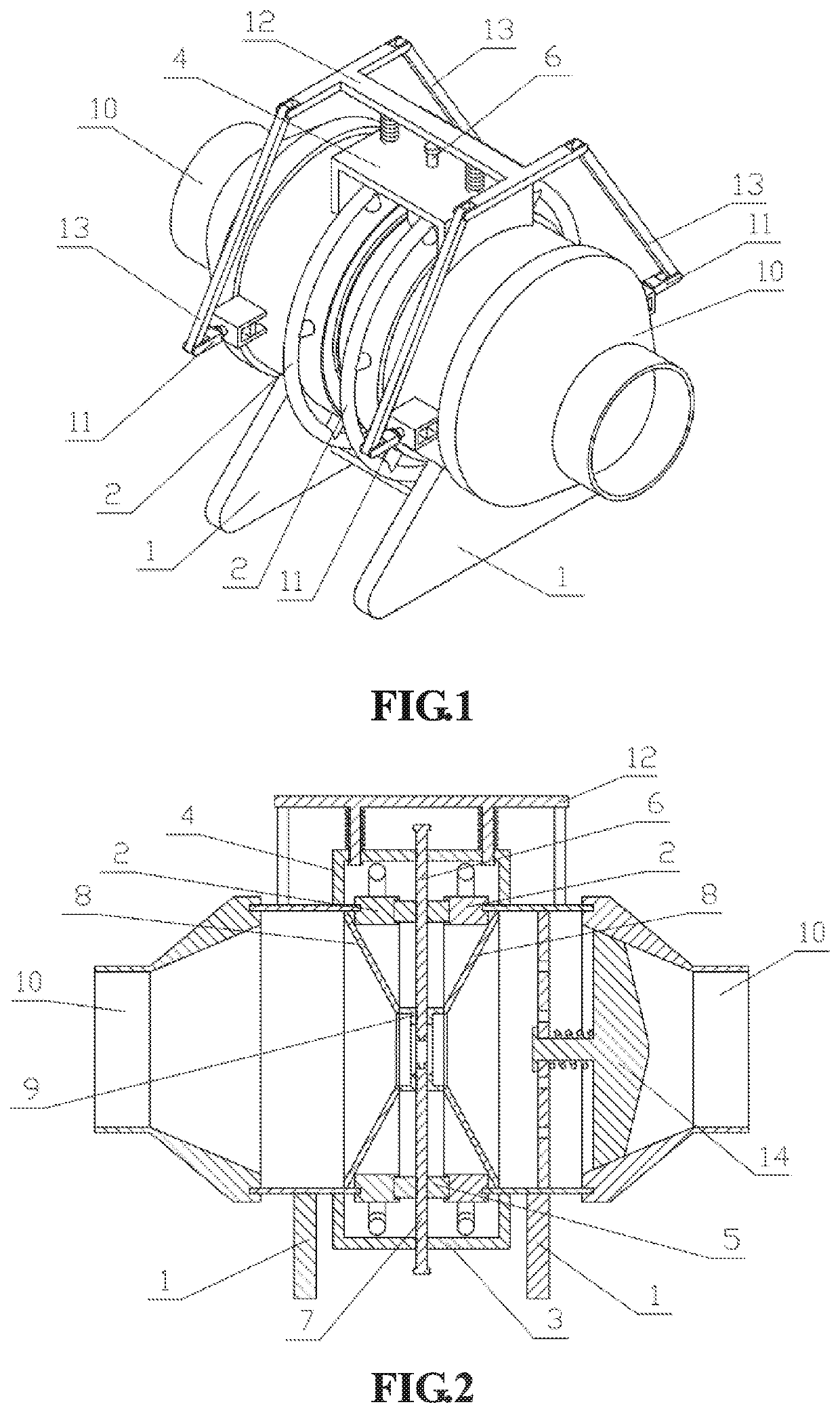
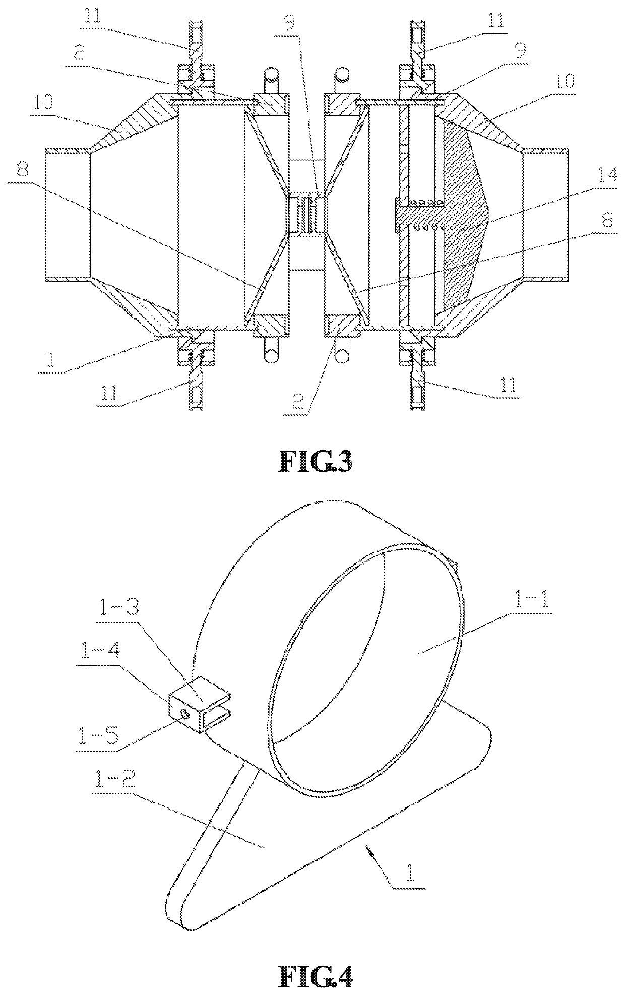
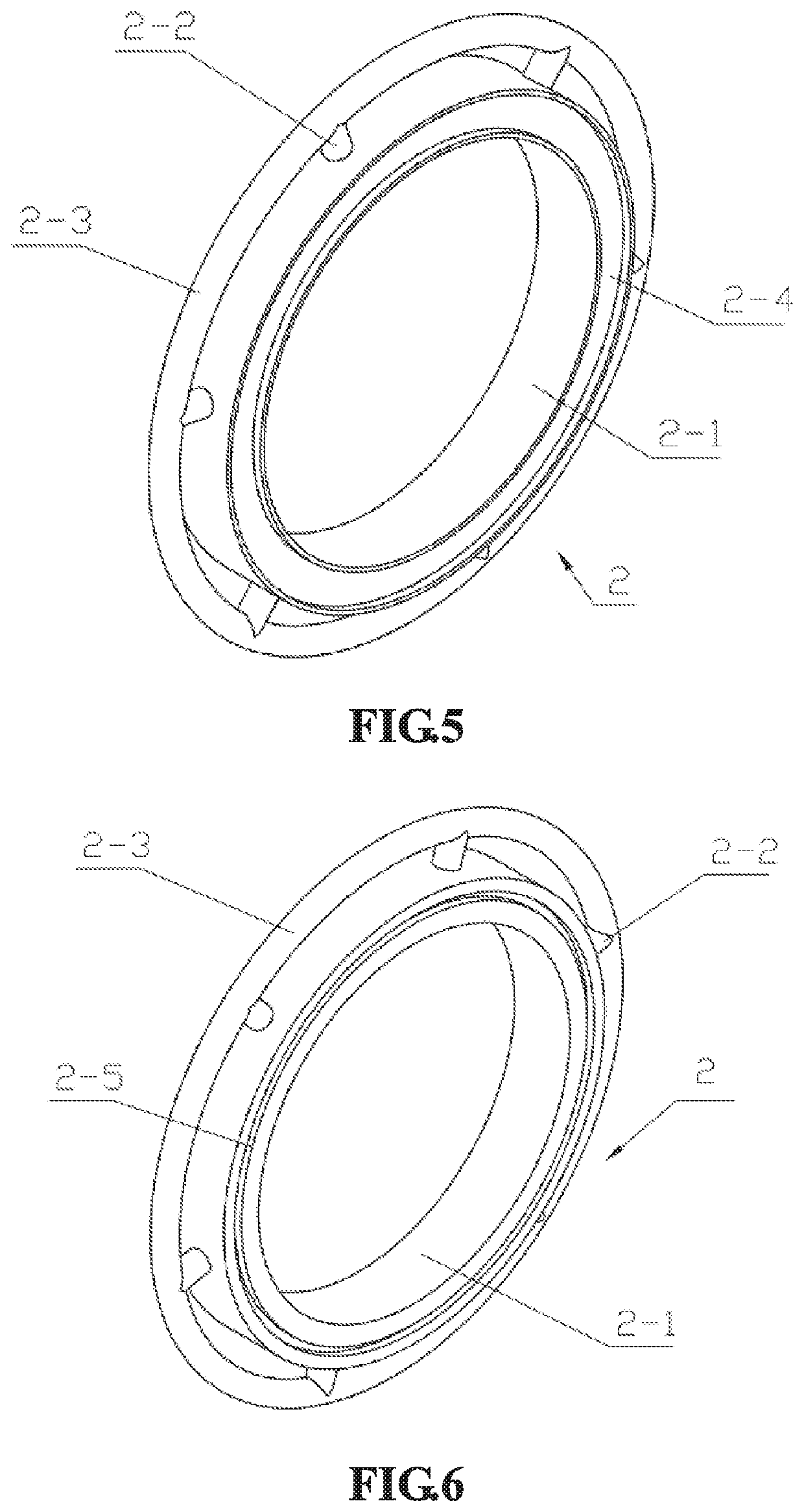
[0040]The present embodiment is described below with reference to FIGS. 1-18, the anti-leakage self-sealing valve comprises a valve support 1, a rotary gear 2, a lower connecting plate 3, an upper connecting plate 4 and a pinion 5, an upper closing plate 6, a lower closing plate 7 and a conical connecting cylinder 8, a connecting support 9, a connecting cylinder 10, a clamping mechanism 11 and a disassembling mechanism 12, a connecting rod 13 and a one-way mechanism 14, and is characterized in that the valve support 1 and the rotary gear 2 are respectively and symmetrically provided with two, and the two rotary gears 2 are respectively and rotationally connected to the inner sides of the two valve supports 1, the left end and the right end of the lower connecting plate 3 are fixedly connected to the two valve supports 1 respectively. The l...


PUM


Abstract

The invention relates to a valve, in particular to an anti-leakage self-sealing valve which comprises a valve support, a rotary gear, a lower connecting plate, an upper connecting plate, a pinion, an upper closing plate, a lower closing plate and a conical connecting cylinder, a connecting support, a connecting cylinder, a clamping mechanism, a disassembling mechanism, a connecting rod and a one-way mechanism.

Description

CROSS REFERENCE TO RELATED APPLICATION[0001]This application claims priority from Chinese Patent Application No. 201810630606.1, filed Jun. 19, 2018 and entitled “ANTI-LEAKAGE SELF-SEALING VALVE” the disclosure of which is hereby incorporated entirely herein by reference.FIELD OF THE INVENTION[0002]The invention relates to a valve, in particular to an anti-leakage self-sealing valve.BACKGROUND OF THE INVENTION[0003]For example, the patent number CN201720091458.1 is an anti-leakage self-sealing valve which comprises a valve body. An upper cover is arranged at the top end of the valve body, and a first groove is formed in the bottom of the upper cover, a second groove is formed in the top of the valve body, and a fixing pin is arranged in the first groove, a fixing hole is formed in the second groove, and the fixing hole is matched with the fixing pin, a sealing ring is arranged at the top of the upper cover, and a vertical downward hollow pipe is arranged in the middle of the sealing...

Claims


Application Information

Patent Timeline
Patent Type & Authority Applications(United States)
IPC IPC(8): F16K31/53F16K31/60
CPCF16K31/60F16K31/53F16K15/06F16K27/0209F16K3/029F16K3/30F16K27/044F16K41/04F16K3/0281
Inventor HAN, ZHENGHAIHAN, WENHAOHAN, WENWENHAN, YUHAN, SHENG
Owner JIANGSU SUYAN VALVE MASCH CO LTD
Why Eureka
Try Eureka