

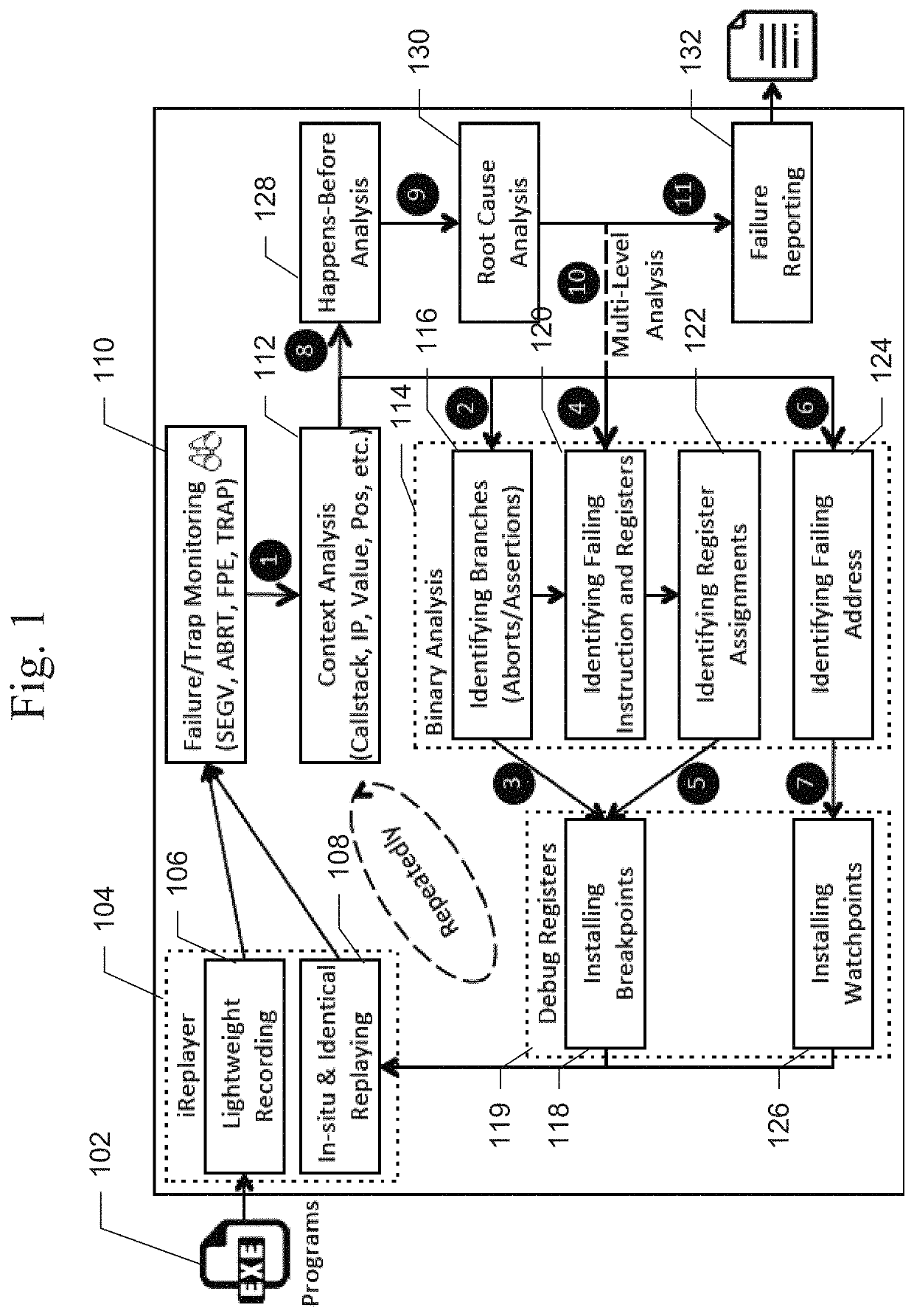
Watcher: precise and fully-automatic on-site failure diagnosis
a software failure and onsite software technology, applied in the field of precise and fully automatic onsite software failure diagnosis, can solve the problems of consuming substantial amounts of overall development cost and developers' time, difficult to diagnose in-production software failures, and difficult to diagnos
- Summary
- Abstract
- Description
- Claims
- Application Information
AI Technical Summary
Benefits of technology
Problems solved by technology
Method used
Image

Examples
Embodiment Construction
[0027]In the following detailed description of the preferred embodiments, reference is made to the accompanying drawings, which form a part hereof, and within which are shown by way of illustration specific embodiments by which the invention may be practiced. It is to be understood that other embodiments may be utilized and structural changes may be made without departing from the scope of the invention. Electrical, mechanical, logical, and structural changes may be made to the embodiments without departing from the spirit and scope of the present teachings. The following detailed description is therefore not to be taken in a limiting sense, and the scope of the present disclosure is defined by the appended claims and their equivalents.
[0028]The techniques described herein may provide techniques for precise and fully-automatic on-site software failure diagnosis that overcomes issues of existing systems and general challenges of in-production software failure diagnosis.
[0029]Embodime...
PUM
 Abstract
Description
Claims
Application Information