Unlock instant, AI-driven research and patent intelligence for your innovation.

Electronic device including a plurality of switches selectively connecting antenna having a plurality of feeding terminals with communication circuit, and driving method thereof

a technology of switching switch and communication circuit, which is applied in the direction of polarisation/directional diversity, individual energised antenna array, particular array feeding system, etc., can solve the problem of inability to efficiently utilize the antenna elements in a time division duplex (tdd) environment, the strength of the signal that is received or transmitted by the antenna, and the inability to utilize a part of the path in an environmen

Active Publication Date: 2019-12-19
SAMSUNG ELECTRONICS CO LTD
View PDF0 Cites 12 Cited by
  • Summary
  • Abstract
  • Description
  • Claims
  • Application Information

AI Technical Summary

Benefits of technology

The patent text describes an electronic device with an antenna that has multiple feeding ports for wireless communication. The device includes a switch that selectively connects the first transmitter and the first receiver with the first feeding port through a specified wire path for a specified frequency. The second transmitter and the second receiver are connected with the second feeding port through a separate wire path. This allows for more efficient communication with different wireless communication circuits that use the specified frequency. The device also includes a phase delay feature for improved communication performance. The technical effects of this invention are improved wireless communication efficiency and better performance in wireless communication circuits.

Problems solved by technology

In the case where the antenna elements receiving a signal and the antenna elements transmitting a signal are separated from each other, it may be impossible to efficiently utilize the antenna elements in a time division duplex (TDD) environment.
In this case, it may be impossible to utilize a part of paths in an environment where a signal that is received or transmitted by an antenna of the electronic device is polarized in a specified direction or where strength of the signal that is received or transmitted by the antenna is weak.
The electronic device fails to control feeding ports respectively positioned at antenna elements, thus failing to change reception strength or phase of the horizontal polarization path or failing to turn off a path itself.
As such, the electronic device that supports the MIMO technology may unnecessarily supply a power to a plurality of antenna elements, thereby wasting a power (or causing an increase of power consumption).

Method used


Image

  • Electronic device including a plurality of switches selectively connecting antenna having a plurality of feeding terminals with communication circuit, and driving method thereof
  • Electronic device including a plurality of switches selectively connecting antenna having a plurality of feeding terminals with communication circuit, and driving method thereof
  • Electronic device including a plurality of switches selectively connecting antenna having a plurality of feeding terminals with communication circuit, and driving method thereof

Examples


Embodiment Construction

[0028]Hereinafter, various example embodiments of the disclosure will be described with reference to accompanying drawings. However, those of ordinary skill in the art will recognize that various modifications, equivalents, and / or alternatives on various example embodiments described herein can be variously made without departing from the scope and spirit of the disclosure.

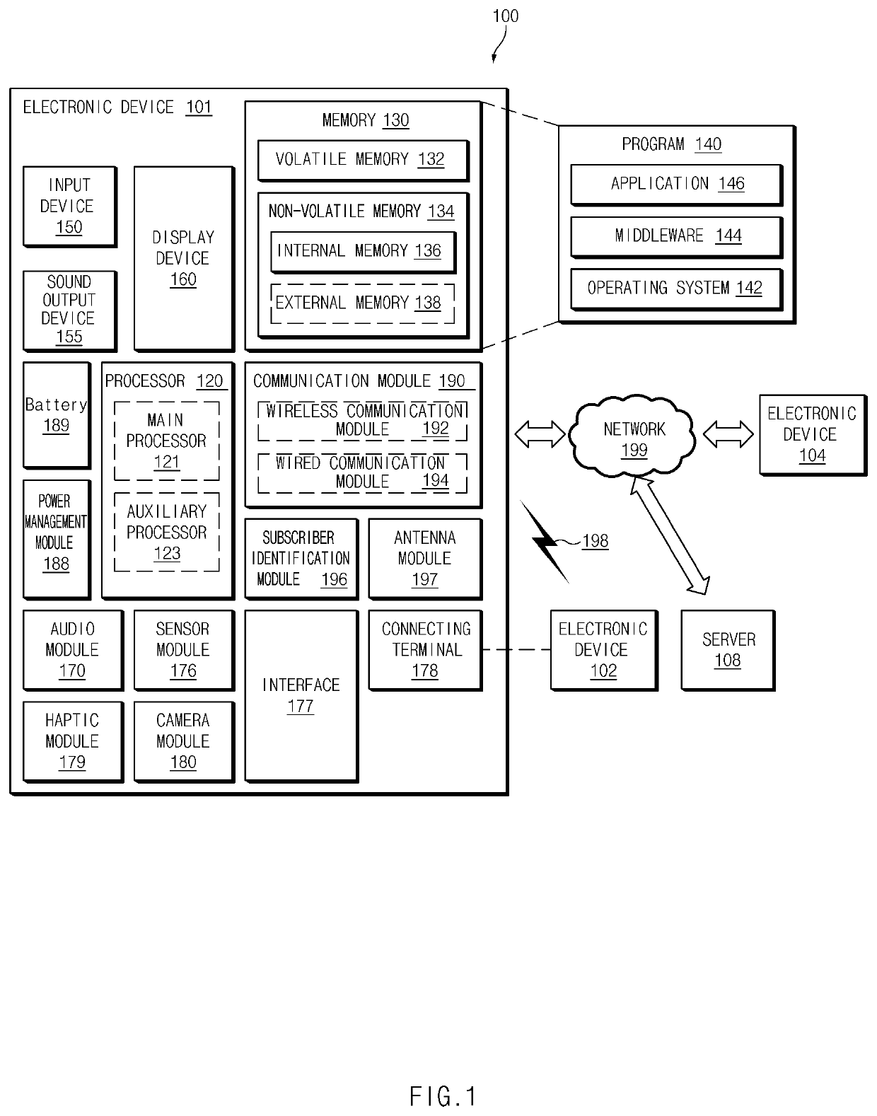
[0029]FIG. 1 is a block diagram illustrating an example electronic device 101 in a network environment 100 according to various embodiments.

[0030]Referring to FIG. 1, the electronic device 101 in the network environment 100 may communicate with an electronic device 102 via a first network 198 (e.g., a short-range wireless communication network), or an electronic device 104 or a server 108 via a second network 199 (e.g., a long-range wireless communication network). According to an embodiment, the electronic device 101 may communicate with the electronic device 104 via the server 108. According to an embodiment, th...


PUM


Abstract

Disclosed is an electronic device. The electronic device includes an antenna including a radiation part comprising a radiator having a patch shape, a first feeding port provided in a first direction of the radiation part, a second feeding port provided in a second direction perpendicular to the first direction of the radiation part, a third feeding port provided in a direction facing away from the first direction, and a fourth feeding port provided in a direction facing away from the second direction, a wireless communication circuit that includes a first communication circuit and a second communication circuit, the first communication circuit including a first transmitter and a first receiver and the second communication circuit including a second transmitter and a second receiver, a first switch configured to selectively connect the first transmitter and the first receiver with the first feeding port, a second switch configured to selectively connect the first transmitter and the first receiver with the second feeding port, a third switch configured to selectively connect the second transmitter and the second receiver with the third feeding port, and a fourth switch configured to selectively connect the second transmitter and the second receiver with the fourth feeding port.

Description

CROSS-REFERENCE TO RELATED APPLICATION[0001]This application is based on and claims priority under 35 U.S.C. § 119 to Korean Patent Application No. 10-2018-0069994, filed on Jun. 19, 2018, in the Korean Intellectual Property Office, the disclosure of which is incorporated by reference herein its entirety.BACKGROUND1. Field[0002]The disclosure relates to a technology for improving reception performance and transmission performance in an environment where a signal that is received or transmitted by an antenna array is polarized in a specific direction or where strength of the signal that is received or transmitted by the antenna array is weak.2. Description of Related Art[0003]As mobile communication technologies develop, an electronic device, which is equipped with an antenna, such as a smartphone, a wearable device, or the like is widely supplied. The electronic device may receive or transmit a signal including data (e.g., a message, a photo, a video, a music file, a game, and the l...

Claims


Application Information

Patent Timeline
Patent Type & Authority Applications(United States)
IPC IPC(8): H01Q21/00H01Q5/10H01Q1/22H01Q21/06
CPCH01Q21/0006H01Q5/10H01Q21/061H01Q1/2283H04B7/0404H04B7/061H04B7/0802H04B1/006H04B1/40H01Q9/045H01Q21/245H04B7/10H04B7/082H04B7/0608H01Q9/0407H01Q3/36
Inventor SON, JUNGHWANKIM, JIYONGNA, HYOSEOKAN, YONGJUN
Owner SAMSUNG ELECTRONICS CO LTD