Smart Electrical Wire-Devices and Premises Power Management System

a technology of smart electrical wire devices and power management systems, applied in non-electric variable control, process and machine control, instruments, etc., can solve the problems of expensive proprietary hardware and software components, not enabling the user to remotely control the device, and not enabling the user to remotely monitor the device in a manner analogous, so as to achieve the effect of maximizing the effectiveness of the system

Active Publication Date: 2010-06-10
DALCHEMY INC
View PDF24 Cites 105 Cited by
  • Summary
  • Abstract
  • Description
  • Claims
  • Application Information

AI Technical Summary

Benefits of technology

[0014]Another advantage of the present invention is accomplished in the situation where the premises micro-grid includes a local source or store of electrical power, such as a local photo-voltaic array or a battery bank. Local, on-site generation of electricity, via solar photo-voltaics (PV's), wind, hydroelectric, etc. is an increasingly important source of power for most electrical power distribution systems. The ability to monitor and control these methods of local generation is necessary in order to maximize the effectiveness of the system. Locally generated electricity often is provided as DC power (e.g., from a battery or a PV source). In these cases, a DC-AC inverter is required to convert the DC power to AC power typically used on a premises micro-grid. A “smart” inverter embodying the management node of the present invention provides a solution for monitoring, and control of a local DC power source. By measuring the electrical characteristics (power, voltage, current, phase, frequency, power factor, etc.) at both the input and output of the inverter, measurements for the power generated, power supplied, and inverter efficiency and phase-locking can be provided. Control at the inverter location provides the ability to electrically disconnect, shunt, or otherwise limit / vary the amount of electrical power supplied.
[0015]Additionally, the ability to communicate with the inverter allows the inverter to be networked into the present power management system. The management node of the smart inverter provides the ability to communicate with the present power management system via the described I / O methods. The smart inverter management node can also communicate directly with the inverter's internal circuitry via an integral serial connection. This provides the inverter with the ability to communicate to the user data in addition to data from the sensors 46a, 46b; additional data such as: inverter circuitry state, inverter health, and diagnostic data related to the inverter circuitry.
[0016]Furthermore, it is an advantage of the present system to provide a means accomplishing the reverse operation of the inverter: i.e., a rectifying device which converts the AC power of the micro-grid to DC power for use or storage locally. This is accomplishable by substituting a rectifying device for or adding a rectifying device to the inverter element 22 in FIG. 9. The rectifying device in practice can be used, for example, to charge a battery bank or other energy storage mechanism. The rectifying device will benefit from the aforementioned monitoring and control capabilities provided by the management node.

Problems solved by technology

However, the electrical power distribution grids of electrical utility providers are not the only points at which meaningful electrical energy efficiencies need to be accomplished.
In large industrial and commercial facilities, such visibility and control are often accomplish using very expensive proprietary hardware and software components not available to residential and small business consumers.
Additionally, the components should not require skill to install that is beyond that of ordinary electrician installer, and once installed should be unobtrusive in the environment of the premises.
Although, these devices may be useful for their intended purpose, to visually monitor the electrical energy consumption of an individual appliance, these and similar devices do not enable the user to remotely (at a distance) monitor the device in a manner analogous to how a power company remotely monitors multiple devices.
More importantly, these and similar devices do not enable the user to remotely control the device in a manner analogous to how a power company remotely controls devices on its power grid.
Therefore, these types of device cannot accomplish the real-time visibility and remote management capability for the consumer, analogous to that which a utility has over the devices on its distribution grid.
However, these devices do not enable granular visibility and control of all or a substantial portion of individual loads on a premise' grid—it is not the individual load component or appliance that is monitored, only the usage of the line.
Therefore, these devices and the systems using them cannot provide the degree of granular visibility to residential user necessary to accomplish energy usage efficiencies analogous to that which a utility has over its distribution grid.
Rodenberg discloses a distribution panel circuit breaker monitoring device wherein the overall power usage of the drop-side of the breaker is monitored, but which cannot monitor the usage of the individual appliances on the drop.
Therefore, the Rodenberg device fails to provide the granular visibility analogous to a utility provider's efficiency system.
It cannot monitor the usage of the individual appliances on the drop.
Therefore, the Hunter device also fails to provide the granular visibility analogous to a utility provider's efficiency system.

Method used


Image

  • Smart Electrical Wire-Devices and Premises Power Management System
  • Smart Electrical Wire-Devices and Premises Power Management System
  • Smart Electrical Wire-Devices and Premises Power Management System

Examples


Embodiment Construction

[0029]Referring now to the drawings, the details of preferred embodiments of the present invention are graphically and schematically illustrated. Like elements in the drawings are represented by like numbers, and any similar elements are represented by like numbers with a different lower case letter suffix.

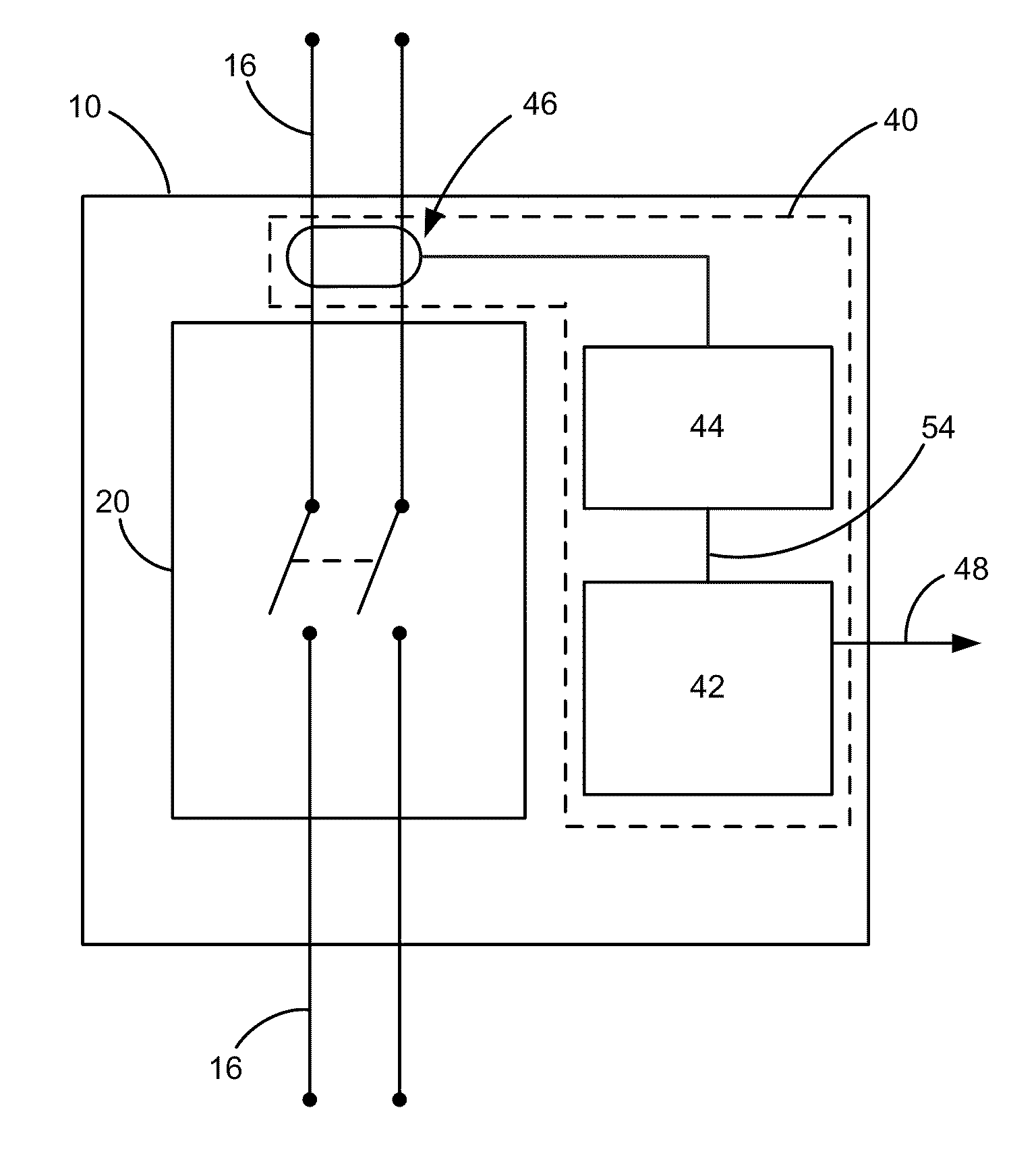
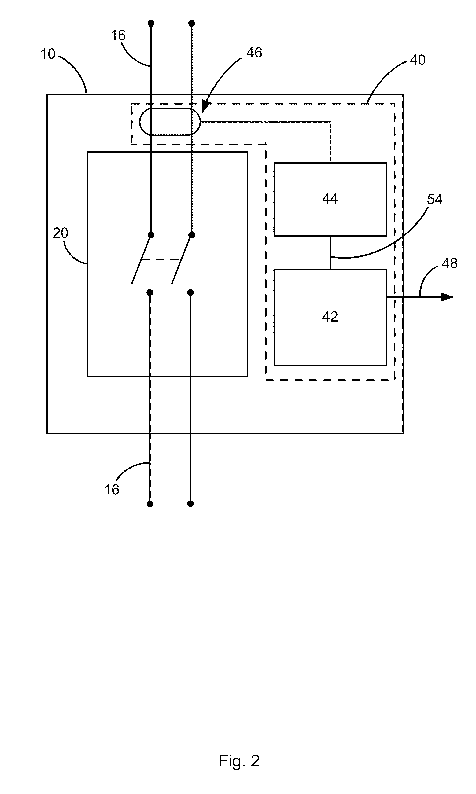
[0030]Referring now to FIG. 2, a preferred embodiment of the present invention is a Smart Wire-Device 10. The Smart Wire-Device 10 is intended to be installable in an electric power line 16 at a consumer premises, i.e., on the drop-side of the electrical utility service at an end consumer's location (premises). An end user's location is the consumer's business premises, residence, shop location and the like. In this embodiment, the Smart Wire-Device 10 is used for measuring an electrical property of the consumer premises electric power line 16 at a point in the power line 16, and to communicate that measurement to an external device (such as a receiver / processor, computer device 1...


PUM


Abstract

Disclosed is power management system based on a “smart” wire-device installable in an electric power line (i.e., the “drop-grid” or “micro-grid”) at a premises, such as a business or residence. The “smart” wire-device includes a management node integrated into the form of a typical electrical power outlet, circuit breaker or switch as would be found in such a premises, and is installable in the power line in a manner similar to existing wire-device. The “smart” wire-device requires no special skill to install beyond that of an ordinary skilled electrician. The present wire-device is “smart” in that the node has a detector circuit that senses the electrical characteristic(s) of the power line at the point at which it is installed. The node's communications circuit signals what it detects to a spatially separated remote controller device, and receives instructions from one or more spatially separated remote controller devices. The node's control mechanism operates a remotely controllable maker / breaker means in response to the received instructions to alter the condition of the electrical power output of the wire-device.

Description

[0001]The present application claims the benefit of prior filed U.S. patent application Ser. No. 12 / 508,569 filed 24 Jul. 2009, to which the present application is a US Continuation-in-Part application; and prior filed U.S. patent applications Ser. No. 12 / 251,449 filed 14 Oct. 2008; 61 / 181,292 filed 27 May 2009; 61 / 100,258 filed 25 Sep. 2008; and International Patent Application serial number PCT / US08 / 79895 filed 14 Oct. 2008, and which prior applications are incorporated herein by reference.FIELD OF THE INVENTION [0002]The present invention is in the field of devices for measuring and testing of one or more electric properties, e.g., kilowatt hour demand / usage (Class 324) of a wire device. Specifically, the present invention relates to electrical usage measurement devices that sense electricity, per se, and signal the result of the measurement for exhibiting and / or processing (Subclass 76.11), and condition responsive control of the wire device.BACKGROUND OF THE INVENTION[0003]The ...

Claims


Application Information

Patent Timeline
Patent Type & Authority Applications(United States)
IPC IPC(8): G06F1/30G06F1/28
CPCG01R19/2513H02J3/14H02J13/0006Y04S20/242Y04S20/222Y02B70/3266Y02B70/3225H02J2310/10Y02B70/30H02J2310/60H02J13/00002H02J13/00016Y04S40/124Y02B90/20Y02A30/60
Inventor MASTERS, GILBERT J.PERNIA, MARCOS S.
Owner DALCHEMY INC
Why Eureka
Try Eureka