
Piping layout for water steam cycle system of combined cycle power plant

a technology of combined cycle power plant and piping layout, which is applied in the direction of steam engine plant, machine/engine, mechanical equipment, etc., can solve the problems of complex structure, complex layout of piping for various steam flows, and inability to provide much flexibility in piping layou

Active Publication Date: 2019-12-26
GENERAL ELECTRIC CO
View PDF8 Cites 1 Cited by
  • Summary
  • Abstract
  • Description
  • Claims
  • Application Information

AI Technical Summary

Benefits of technology

The present disclosure aims to address certain problems and provide solutions. The technical effects of the patent text are designed to address the specific issues that were previously present.

Problems solved by technology

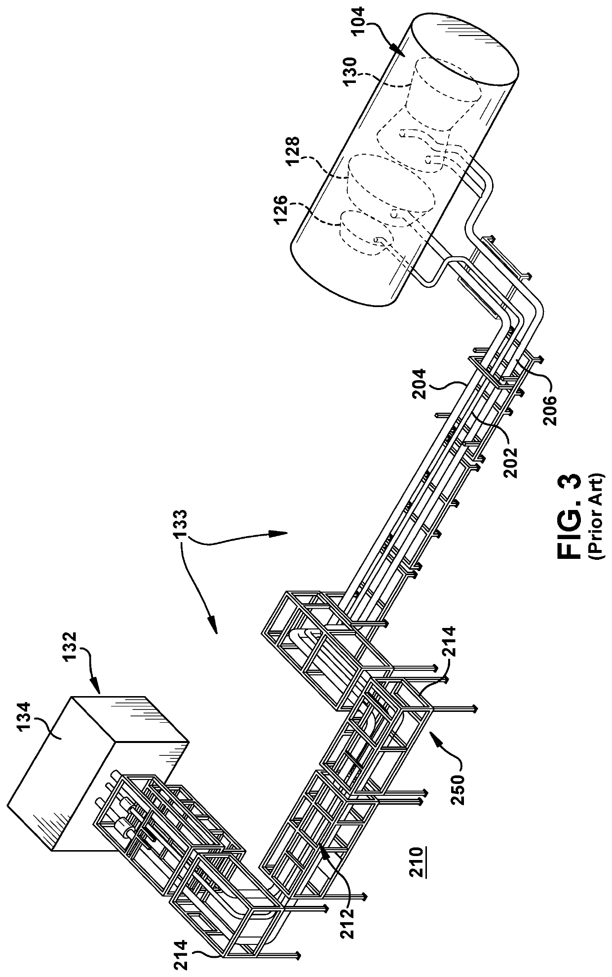
Piping for the various steam flows typically require very complex layouts in order to address a number of challenges.
Consequently, the piping enters the admission valves of the steam turbine segments from vertically below, which does not provide much flexibility in the piping layout because the floor is close by.
Second, the piping layouts require routing from the HRSG to the respective steam turbine and other structure such as a de-superheater around other structure in the CCPP, e.g., other piping, support structures, parts of the gas or steam turbine systems and ancillary devices such as pumps, air inlets, etc.
In either event, the structures are complex to build and increase the CCPP building size requirements.
In view of the foregoing, piping layouts are typically very complex and expensive to build.
In particular, the length of piping required can be very long.

Method used


Image

  • Piping layout for water steam cycle system of combined cycle power plant
  • Piping layout for water steam cycle system of combined cycle power plant
  • Piping layout for water steam cycle system of combined cycle power plant

Examples


Embodiment Construction

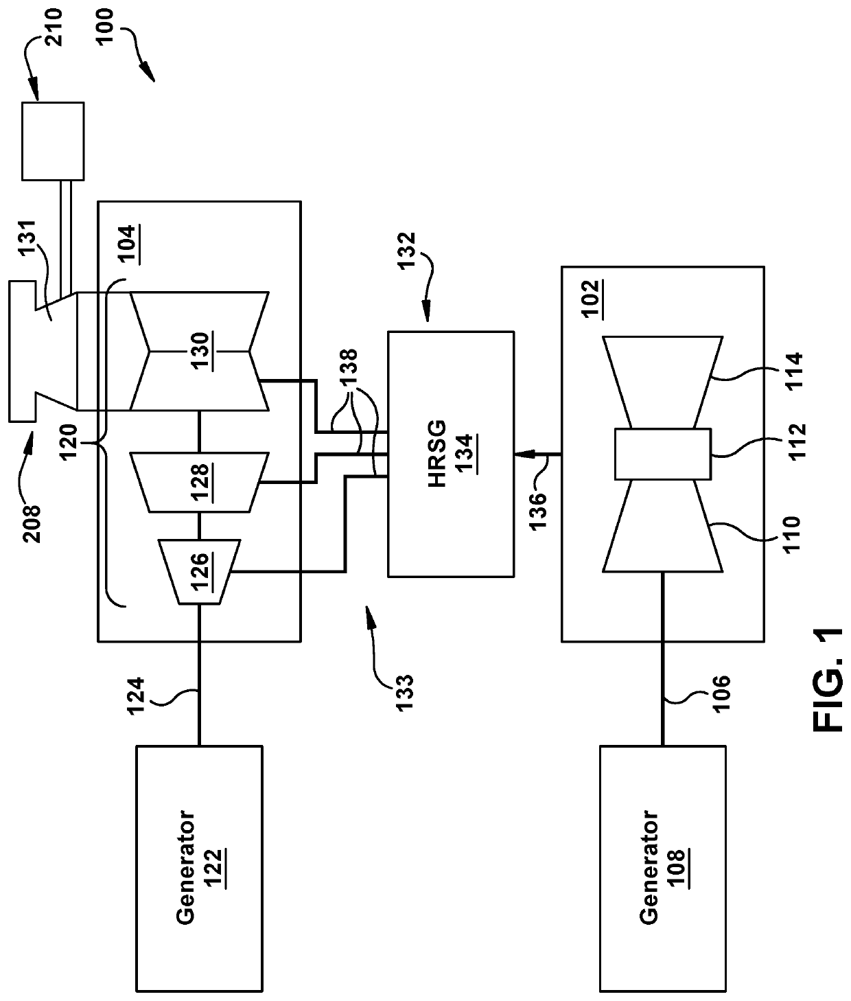
[0024]As an initial matter, in order to clearly describe the current disclosure it will become necessary to select certain terminology when referring to and describing relevant machine components within a water steam cycle (WSC) system, a steam turbine (ST) system and / or a combined cycle power plant. When doing this, if possible, common industry terminology will be used and employed in a manner consistent with its accepted meaning. Unless otherwise stated, such terminology should be given a broad interpretation consistent with the context of the present application and the scope of the appended claims. Those of ordinary skill in the art will appreciate that often a particular component may be referred to using several different or overlapping terms. What may be described herein as being a single part may include and be referenced in another context as consisting of multiple components. Alternatively, what may be described herein as including multiple components may be referred to el...


PUM


Abstract

A piping layout for a water steam cycle (WSC) system of a combined cycle power plant is disclosed. The piping layout includes a first steam flow pipe delivering steam from a steam source to a high pressure (HP) segment of the ST system. The first flow pipe includes a first vertically oriented thermal expansion portion. The WSC system may also include a second steam flow pipe delivering steam from the steam source to an intermediate pressure (IP) segment of the ST system. It may also include a third steam flow pipe delivering steam from HP segment of the ST system to a steam source. The vertically oriented thermal expansion portion(s) may be positioned immediately upstream of the admission valve of the respective segment and / or immediately downstream from an outlet of the steam source.

Description

BACKGROUND OF THE INVENTION[0001]The disclosure relates generally to combine cycle power plants (CCPP), and more particularly, to a piping layout for a water steam cycle system for steam turbine (ST) system of a CCPP.[0002]Combined cycle power plants include a gas turbine system and a steam turbine system that work together to produce energy. The gas turbine system combusts a mixture of fuel with an air flow and directs it through a turbine to generate power. Exhaust from the gas turbine is used in a heat recovery steam generator (HRSG) to create steam that is directed to the steam turbine system to generate power. Piping carries the steam from the HRSG to the steam turbine system. These pipes are part of a water steam cycle (WSC) system. The steam turbine system may have a number of steam turbine segments configured to receive steam from the HRSG with each steam flow having different characteristics. For example, steam may be delivered in a number of steam flow pipes carrying high,...

Claims


Application Information

Patent Timeline
Patent Type & Authority Applications(United States)
IPC IPC(8): F01K13/00F01K3/18F01K13/02F01K23/10
CPCF01K3/185F01K13/02F01K13/006F01K23/106Y02E20/16
Inventor DOKIC, BORISLAVAGRAWAL, PRASHANT
Owner GENERAL ELECTRIC CO
Features
  • Generate Ideas
  • Intellectual Property
  • Life Sciences
  • Materials
  • Tech Scout
  • Unparalleled Data Quality
  • Higher Quality Content
  • 60% Fewer Hallucinations
Learn More