Focusing and leveling device

a leveling device and focus technology, applied in measurement devices, instruments, surveying and navigation, etc., can solve the problems of difficult construction, large footprint, and large footprint of devices, and achieve the effect of simple structure, simple structure and reduced footprint of devices

Active Publication Date: 2019-12-26
SHANGHAI MICRO ELECTRONICS EQUIP (GRP) CO LTD
View PDF11 Cites 2 Cited by
  • Summary
  • Abstract
  • Description
  • Claims
  • Application Information

AI Technical Summary

Benefits of technology

[0015]In the device, by using the deflection prism, the projection- and detection-side 4F systems are arranged on a single side of the substrate, which shrinks the footprint of the device and enhances its compactness. Moreover, the projection-side 4F system is multiplexed, dispensing with a separate detection-side 4F system and hence allowing a simple structure, easy construction and a reduction in fabrication cost. Further, since the probe beam is reflected twice at the substrate surface, the impact of any amount of defocus or tilt on the position of the formed spot is doubled, i.e., doubled measuring accuracy with the same detection ability.

Problems solved by technology

Since the conventional device incorporates two 4F systems arranged on opposing sides of the wafer respectively for projection and detection, it is complicated in structure, bulky, costly and does not allow easy construction.

Method used


Image

  • Focusing and leveling device
  • Focusing and leveling device
  • Focusing and leveling device

Examples


embodiment 1

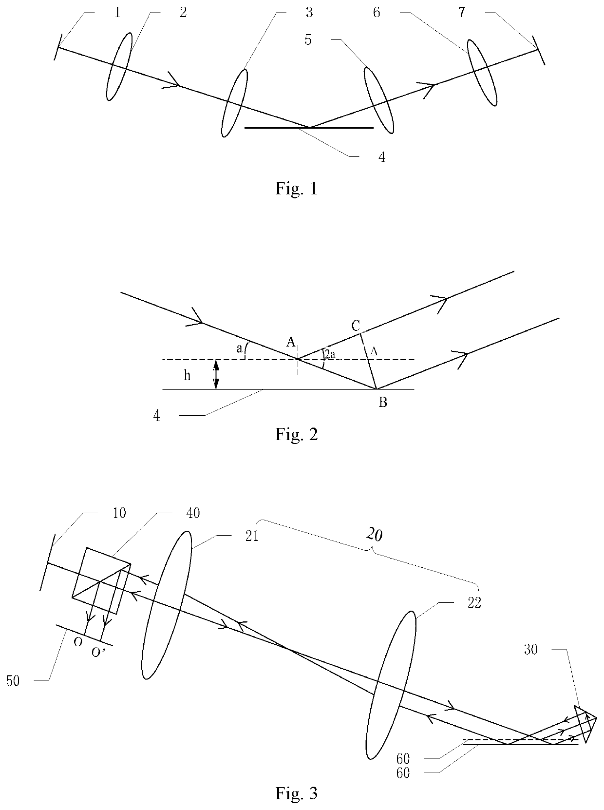
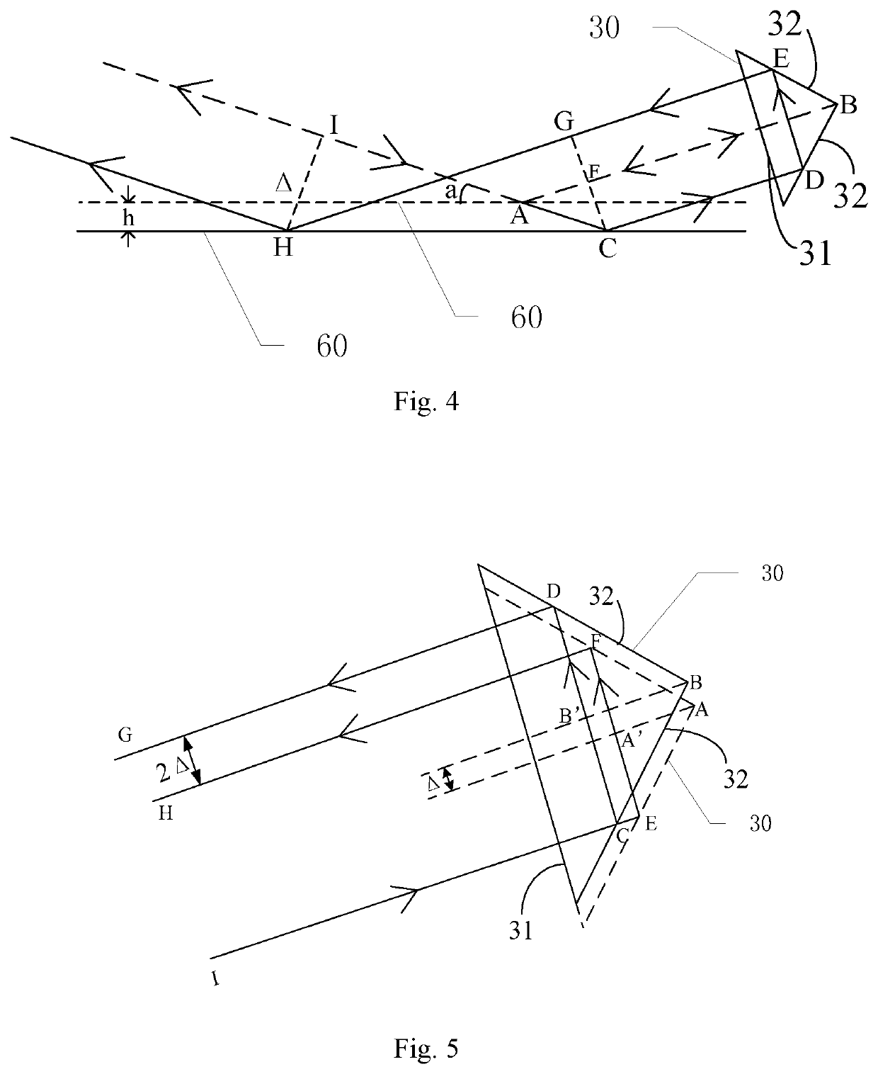
[0025]Referring to FIG. 3, a device for focusing and leveling includes, arranged sequentially along a path of a light beam travelling therein, an illumination unit (not shown), a projection-side mark plate 10 defining therein a projection-side slit mark, a projection-side imaging group 20, a deflection prism 30, a beam splitter 40, a detection unit and a signal processing unit (not shown). Emitted from the illumination unit, the light beam passes through the projection-side mark plate 10 is thus trimmed into a probe beam which then transmits through the beam splitter 40 and is directed by the projection-side imaging group 20 onto the surface of a substrate 60. The deflection prism 30 is configured to deflect the probe beam that has been reflected by the surface of the substrate 60 so that it is again incident on the surface of the substrate 60. The probe beam that has been reflected for the second time on the surface of the substrate 60 travels through the projection-side imaging gr...

embodiment 2

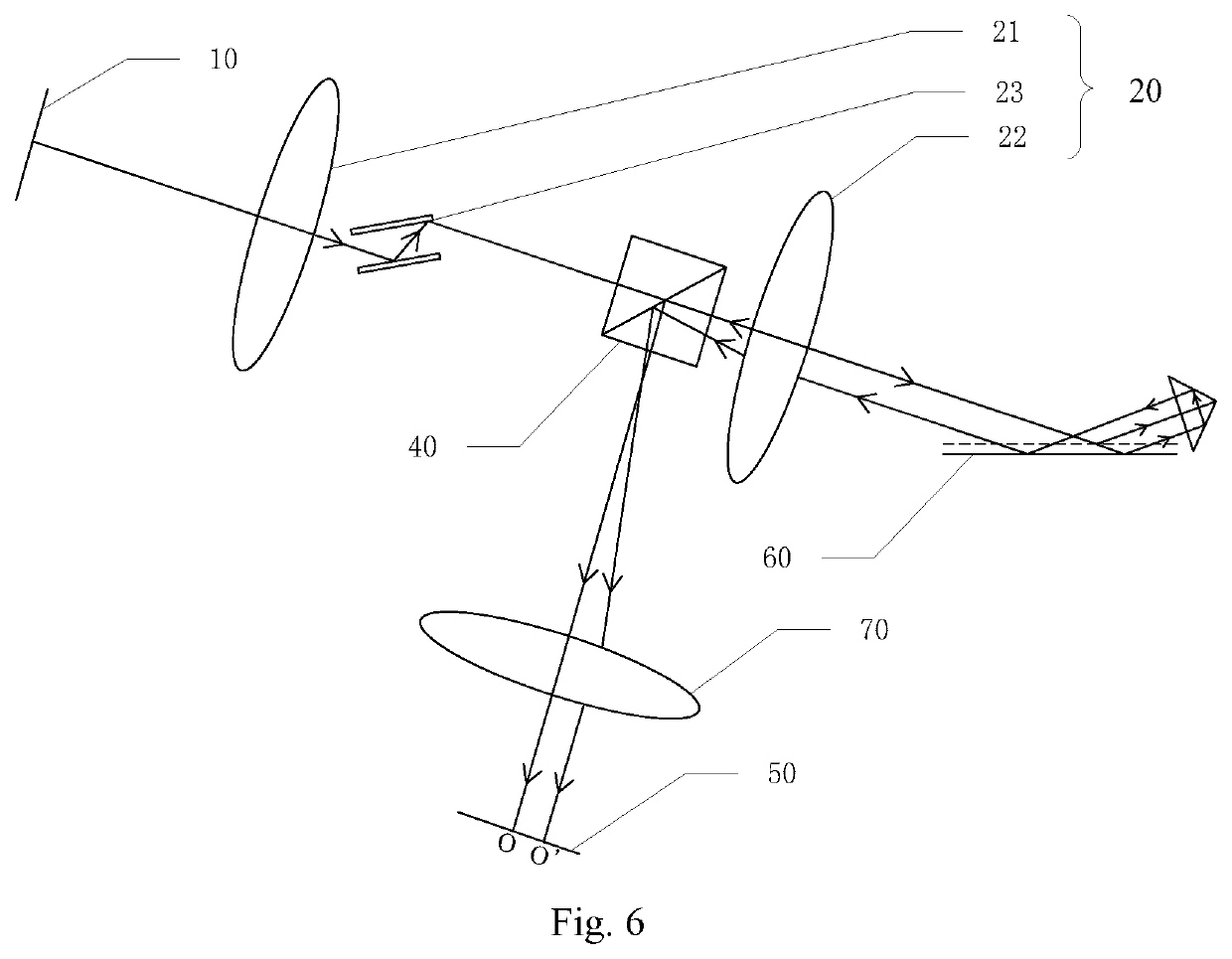
[0036]Referring to FIG. 6, Embodiment 2 differs from Embodiment 1 essentially in the paths of propagation of the probe beam to the surface of the substrate 60 and from the second reflection to the detection-side mark plate 50. Specifically, the projection-side imaging group 20 includes a front lens group 21, a mirror pair 23 and a rear lens group 22. The probe beam from the projection-side mark plate 10 travels sequentially through the front lens group 21, the mirror pair 23, the beam splitter 40 and the rear lens group 22, and is then incident on the surface of the substrate 60. Additionally, subsequent to the reflection on the surface of the substrate 60 for the second time, the probe beam again propagates through the rear lens group 22 and is then reflected by the beam splitter 40 onto the detection-side mark plate 50. The mirror pair 23 according to the embodiment includes a fixed mirror and a moveable mirror capable of changing the exit direction of the probe beam.

[0037]The dev...


PUM


Abstract

A focusing and leveling device calculates an amount of defocus and/or tilt of a substrate and includes an illumination unit, projection-side mark plate with projection-side slit mark, projection-side imaging group, deflection prism, beam splitter, detection unit and signal processing unit. A light beam emitted from the illumination unit passes through the projection-side mark plate and is trimmed into a probe beam directed by the projection-side imaging group onto a substrate surface. The prism deflects the probe beam reflected by the surface of the substrate for a first time so that it is incident on the substrate surface and reflected for a second time onto the projection-side imaging group. The beam splitter directs the probe beam that travelled through the projection-side imaging group onto the detection unit. The signal processing unit calculates the amount of defocus and/or tilt based on a measurement spot detected by the detection unit.

Description

TECHNICAL FIELD[0001]The present invention relates to a device for focusing and leveling.BACKGROUND[0002]FIG. 1 shows a commonly-used conventional device for focusing and leveling, which includes, arranged sequentially along a path of light travelling therein, a projection-side mark plate 1, a projection-side front lens group 2, a projection-side rear lens group 3, a wafer 4, a detection-side front lens group 5, a detection-side rear lens group 6 and a detection-side mark plate 7. Wherein, the projection-side mark plate 1, the projection-side front lens group 2, the projection-side rear lens group 3 and the wafer 4 constitute a 4F system; the wafer 4, the detection-side front lens group 5, the detection-side rear lens group 6 and the detection-side mark plate 7 constitute another 4F system. Light emitted from an illumination unit passes through a mark on the projection-side mark plate 1 and then travels through the projection-side front lens group 2 and the projection-side rear lens...

Claims


Application Information

Patent Timeline
Patent Type & Authority Applications(United States)
IPC IPC(8): G01C9/06
CPCG03F7/70258G01C9/06G03F9/7026G03F9/7034G03F7/20G03F9/00G03F7/70008G03F7/70141G03F7/70241G03F7/70275G03F7/70641
Inventor LAN, KEWANG, SHIHUA
Owner SHANGHAI MICRO ELECTRONICS EQUIP (GRP) CO LTD
Why Eureka
Try Eureka