Control of ionic cooling in wireless charging systems

a wireless charging and control technology, applied in the direction of electrical apparatus construction details, inductances, transportation and packaging, etc., can solve the problems of affecting the environment in which the charger is installed, consuming a large amount of power, and accumulating heat in the transmitting coil

Active Publication Date: 2019-12-26
INTEGRATED DEVICE TECH INC
View PDF0 Cites 27 Cited by
  • Summary
  • Abstract
  • Description
  • Claims
  • Application Information

AI Technical Summary

Problems solved by technology

Often, there is heat buildup in the transmit coils as a result of the charging process.
Cooling the system by conventional means (e.g., mechanical fans) can consume a large amount of power and is noisy, disrupting the environment in which the charger is installed, and is prone to mechanical failure.

Method used


Image

  • Control of ionic cooling in wireless charging systems
  • Control of ionic cooling in wireless charging systems
  • Control of ionic cooling in wireless charging systems

Examples


Embodiment Construction

[0010]In the following description, specific details are set forth describing some embodiments of the present invention. It will be apparent, however, to one skilled in the art that some embodiments may be practiced without some or all of these specific details. The specific embodiments disclosed herein are meant to be illustrative but not limiting. One skilled in the art may realize other elements that, although not specifically described here, are within the scope and the spirit of this disclosure.

[0011]This description and the accompanying drawings that illustrate inventive aspects and embodiments should not be taken as limiting—the claims define the protected invention. Various changes may be made without departing from the spirit and scope of this description and the claims. In some instances, well-known structures and techniques have not been shown or described in detail in order not to obscure the invention.

[0012]Elements and their associated aspects that are described in det...


PUM

PropertyMeasurementUnit
DC voltageaaaaaaaaaa
voltageaaaaaaaaaa
voltageaaaaaaaaaa

Abstract

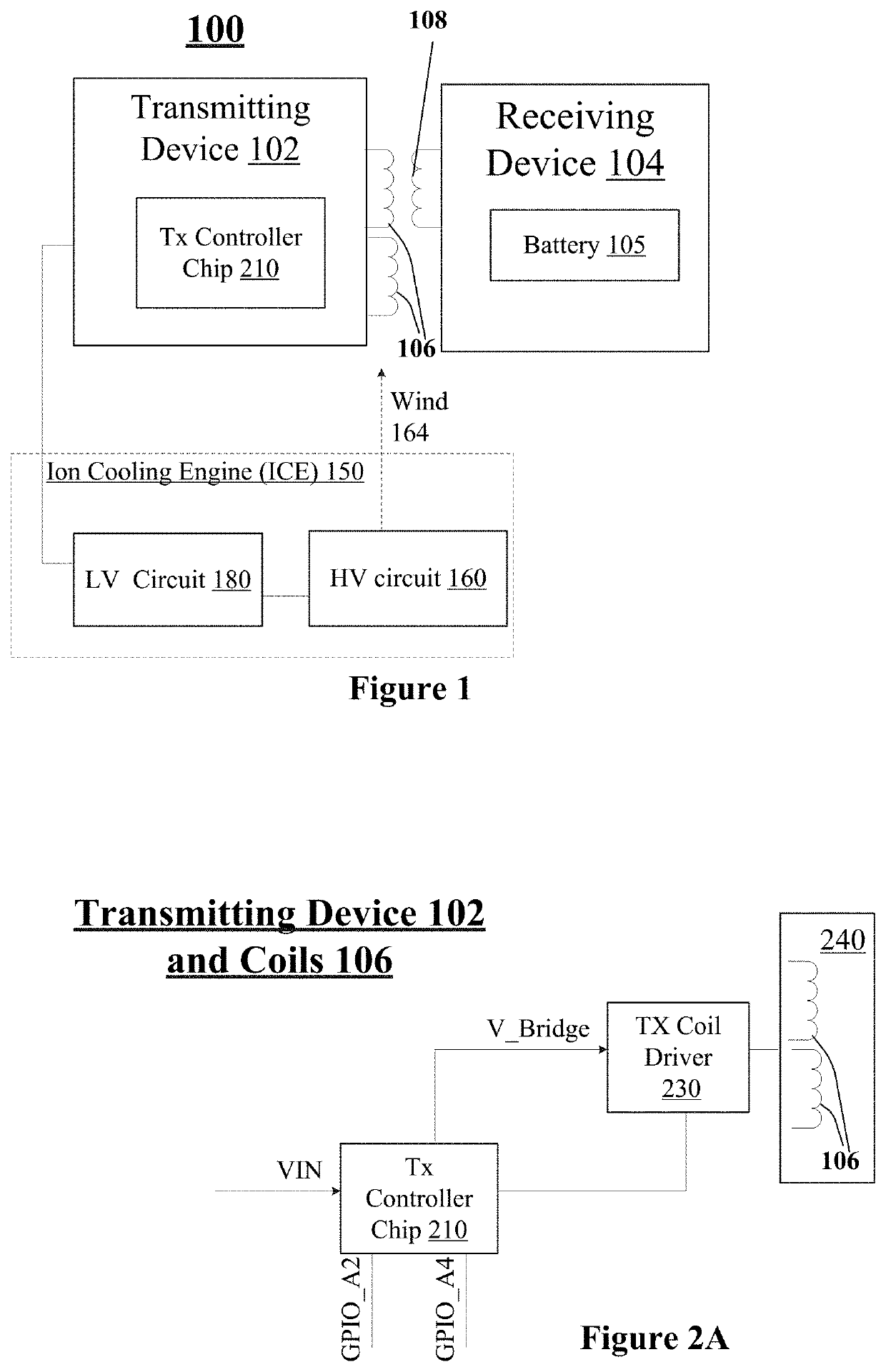
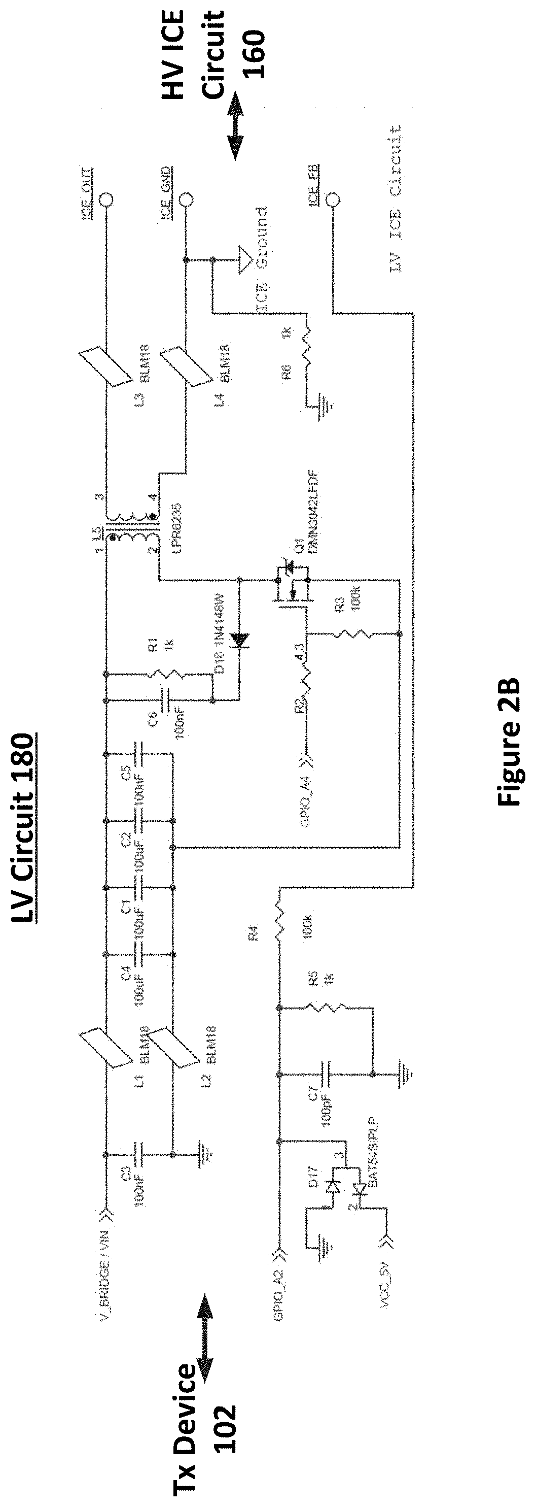
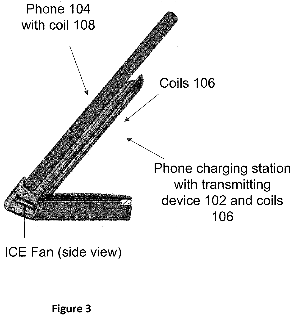
In accordance with some embodiments of the present invention, an ion cooling engine (ICE) controlled by a transmitting or receiving device cools a transmit or receive coil and possibly other parts of a wireless power transmitter or receiver system. In some embodiments, the ICE includes a low-voltage circuit controlled by the transmitting device and coupled to a high voltage circuit that generates the airflow. Other features are also provided.

Description

CROSS REFERENCE TO RELATED APPLICATIONS[0001]The present application claims priority to U.S. provisional patent application No. 62 / 687,693, filed Jun. 20, 2018, incorporated herein by reference.TECHNICAL FIELD[0002]Embodiments of the present invention are related to wireless power systems and, specifically, to cooling of such systems.DISCUSSION OF RELATED ART[0003]Typically, a wireless power system includes a transmitter coil that is driven to produce a time-varying magnetic field and a receiver coil, which can be part of a device such as a cell phone, PDA, computer, or other device, that is positioned relative to the transmitter coil to receive the power transmitted in the time-varying magnetic field. Often, there is heat buildup in the transmit coils as a result of the charging process. Cooling the system by conventional means (e.g., mechanical fans) can consume a large amount of power and is noisy, disrupting the environment in which the charger is installed, and is prone to mech...

Claims


Application Information

Patent Timeline
Patent Type & Authority Applications(United States)
IPC IPC(8): H05K7/20H02J7/02H02J7/00H02J50/60H02J50/10H01F38/14H02J50/90
CPCH02J50/60H02J50/90H02J50/10H02J7/025H02J7/0042H01F38/14H05K7/20945H05K7/20909H01F27/08H02J7/0044H02J50/402
Inventor SMITH, NICHOLAUS WAYNEQI, TAOBAVISI, AMIT D.KIM, CHANGJAE
Owner INTEGRATED DEVICE TECH INC
Why Eureka
Try Eureka