Device for regulating a flow-through and distributing a fluid in a fluid circuit

a fluid circuit and flow-through technology, applied in the direction of valve housings, heat pumps, lighting and heating apparatus, etc., can solve the problems of increasing complexity of the refrigerant circuit of the climate control system, the disposition and placement of the thermal system for conditioning different components, and the large installation spa

Active Publication Date: 2020-01-02
HANON SYST
View PDF0 Cites 0 Cited by
  • Summary
  • Abstract
  • Description
  • Claims
  • Application Information

AI Technical Summary

Benefits of technology

[0037]A further advantage of the invention comprises that axes of symmetry of the outlet openings, in the case of spherical implementation of the valve element, have in each instance the identical inclination referred to the projected center of the spherical shell such that the axes of symmetry of the outlet openings intersect in a common point on an axis of symmetry of the spherical shell or are disposed parallel to one another and to the axis of symmetry of the spherical shell or an axis of symmetry of the circular cylinder.

Problems solved by technology

Specifically, in the case of hybrid-driven motor vehicles, there are encountered great challenges regarding the disposition and placement of the thermal system for conditioning different components within the available installation space.
Specifically, the refrigerant circuits of the climate control systems, or of the thermal systems, of motor vehicles are growing increasingly more complex and include providing energy efficient solutions for conditioning the inflowing air of the passenger compartment, such as cooling, dehumidifying or heating.
The required large number of valves and connection lines demands considerable installation space and, in addition to high costs, also causes a significant weight of the refrigerant circuit.
The highly complex implementation of the two-part valve block arrangement requires additional components, such as sealings, guides and threaded joints, which again leads to high production costs, high susceptibility to errors during assembly, high demands made of leak impermeability and strength and rigidity as well as heavy weight.
It is not possible to control the connections individually independently of one another.

Method used


Image

  • Device for regulating a flow-through and distributing a fluid in a fluid circuit
  • Device for regulating a flow-through and distributing a fluid in a fluid circuit
  • Device for regulating a flow-through and distributing a fluid in a fluid circuit

Examples


Embodiment Construction

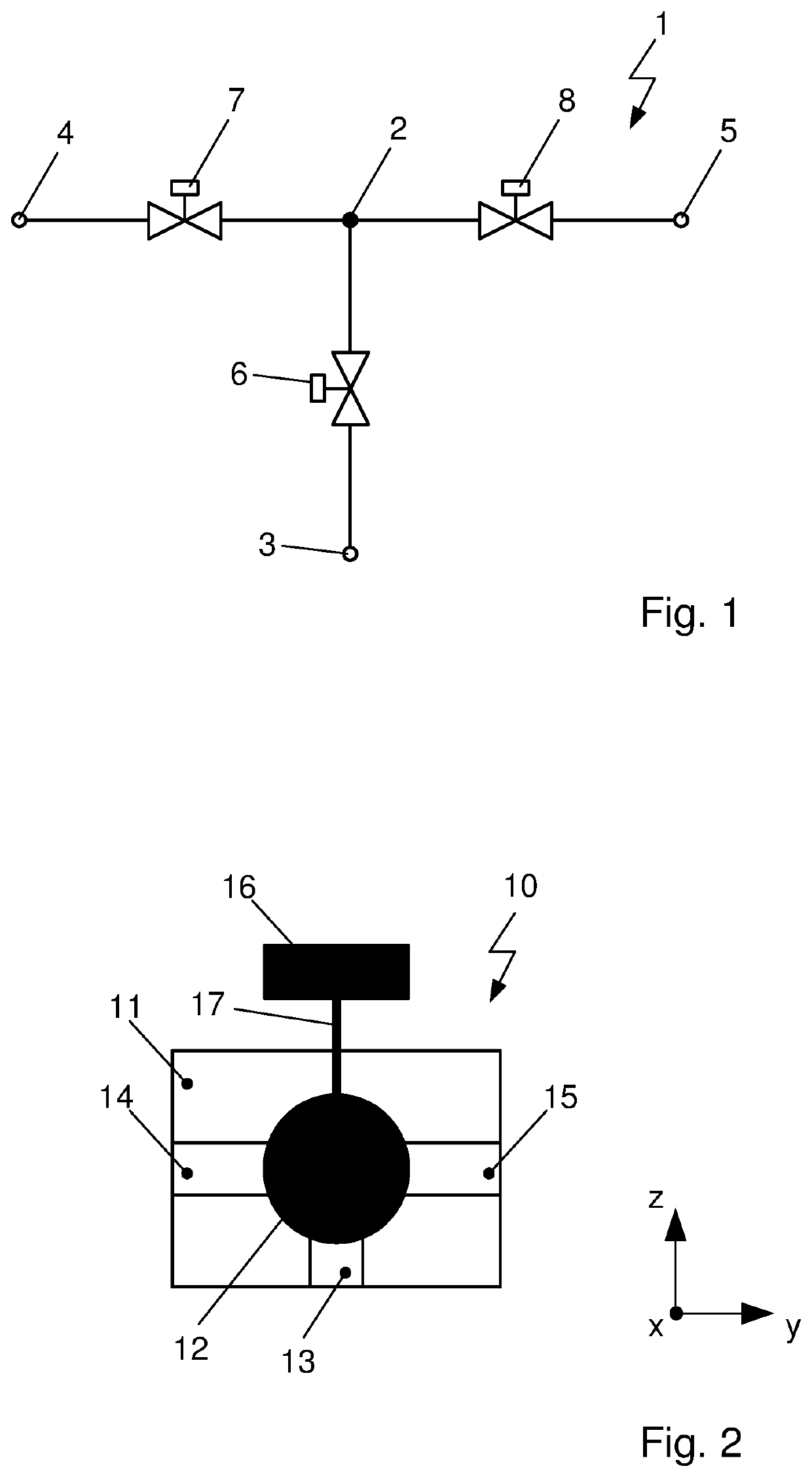
[0068]In FIG. 1 is shown a connection configuration 1 of three valves 6, 7, 8 as a section from a fluid circuit, in particular from a refrigerant circuit of a climate control system of a motor vehicle. The refrigerant circuit can be developed with at least one compressor and in each instance several heat exchangers operable as evaporators or condensers / gas coolers for the transfer of heat with the refrigerant. To each condenser / gas cooler is herein assigned a valve, in particular a check valve, for example a solenoid valve. The components of the refrigerant circuit are fluidically connected with one another across connection lines.

[0069]When the refrigerant in subcritical operation of the refrigerant circuit, such as for example with the refrigerant R134a or under certain ambient conditions with carbon dioxide, is liquified, the heat exchanger is termed condenser. A portion of the heat transfer takes place at constant temperature. In supercritical operation, or at supercritical heat...


PUM


Abstract

Device for regulating and controlling a flow-through and distributing a fluid in a fluid circuit has a housing with ports connecting fluid lines that are connected across a passage aperture with an interior volume of the housing, a valve element disposed in the interior volume of the housing, a drive element for moving the valve element relative to the housing.

Description

FIELD OF THE INVENTION[0001]The invention relates to a device for regulating or controlling a flow-through and distributing a fluid in a fluid circuit, in particular a refrigerant in a refrigerant circuit. The device comprises a housing with ports for the connection with fluid lines, each of which being connected across passage apertures with an interior volume of the housing, as well as a valve element, disposed in the interior volume of the housing, with a drive element for moving the valve element relative to the housing.SUMMARY OF THE INVENTION[0002]In motor vehicles of prior art high demands made of the climate control systems in motor vehicles for the comfort of the passengers in the passenger compartment are met by different circuits for refrigerant and coolant with differently operated heat exchangers.[0003]Conventional and future motor vehicles with electromotive drive, termed electric vehicles or abbreviated EVs, or FCV for “fuel cell vehicles”, or motor vehicles with hybr...

Claims


Application Information

Patent Timeline
Patent Type & Authority Applications(United States)
IPC IPC(8): F16K5/06F25B30/00F16K11/087F25B5/02
CPCF25B30/00F16K11/0873B60H1/039F16K5/0605F25B5/02F16K11/0876F16K5/10B60H1/00485F25B41/20F25B2500/18F25B9/008B60H1/00899B60H1/00278B60H1/3228B60H2001/00307F16K27/067F25B41/40
Inventor SPIES, TONIHAAS, TOBIASWIECHARD, DOMINIKHERZOG, MARKUS
Owner HANON SYST
Why Eureka
Try Eureka