
High visual comfort road and urban LED lighting

Active Publication Date: 2020-01-02
SIGNIFY HOLDING B V
View PDF0 Cites 2 Cited by
  • Summary
  • Abstract
  • Description
  • Claims
  • Application Information

AI Technical Summary

Benefits of technology

The current LED road lighting luminaire systems have a drawback of having a pixelated appearance and a high glare / brightness contrast. The technical effect of this patent text is to provide a solution for this issue and provide a more uniform and evenly lit road surface.

Problems solved by technology

However, a drawback of these systems is the pixelated appearance of the luminaire and the high glare / brightness contrast (high brightness at the lens positions and almost dark in between the lenses).

Method used


Image

  • High visual comfort road and urban LED lighting
  • High visual comfort road and urban LED lighting
  • High visual comfort road and urban LED lighting

Examples


Embodiment Construction

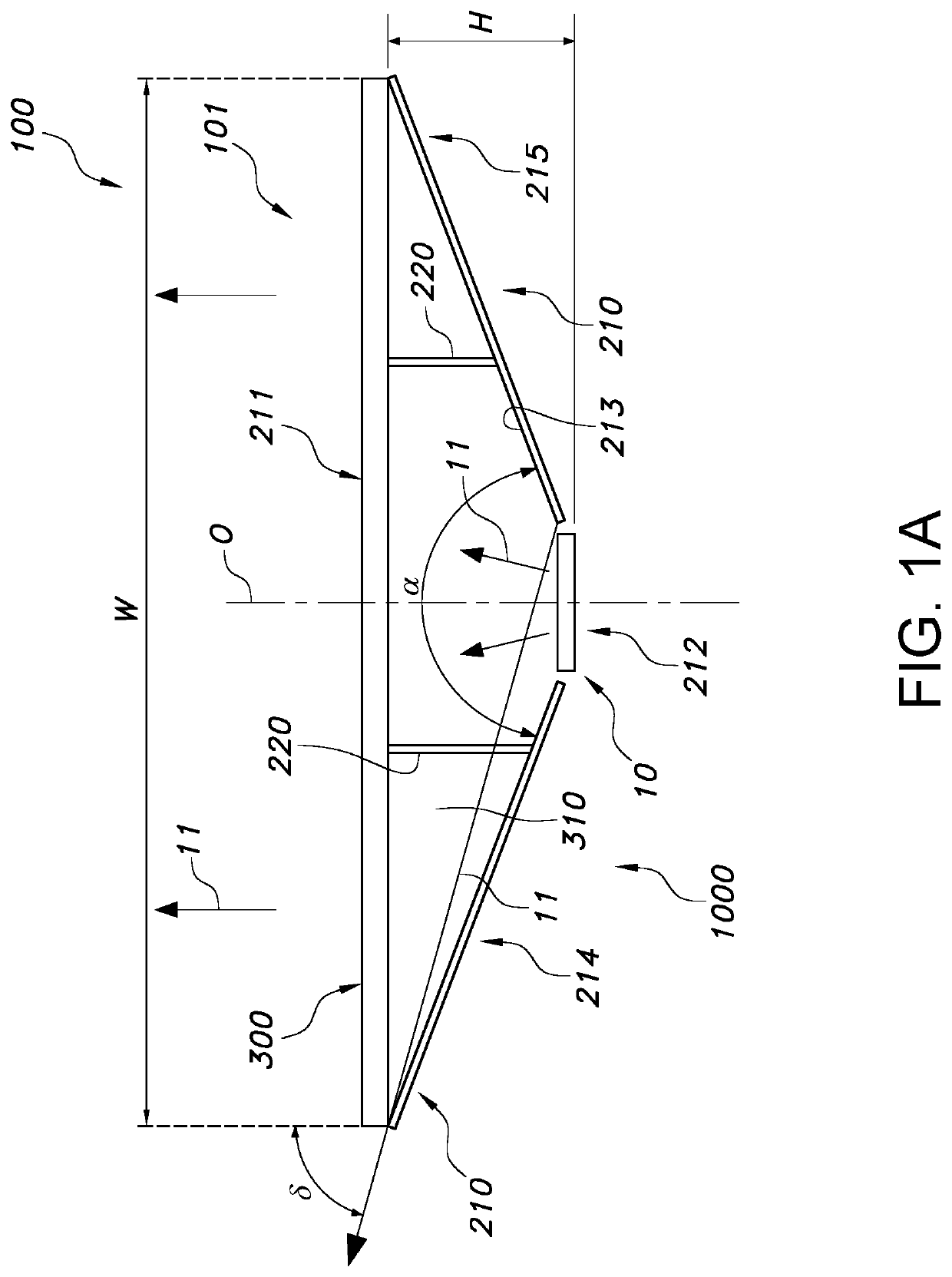
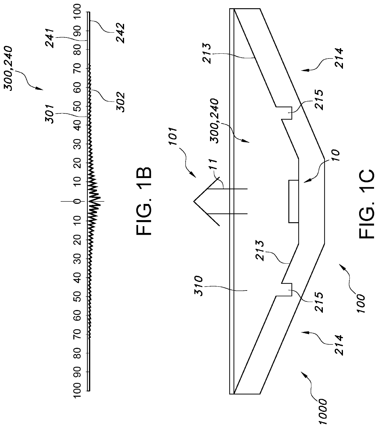
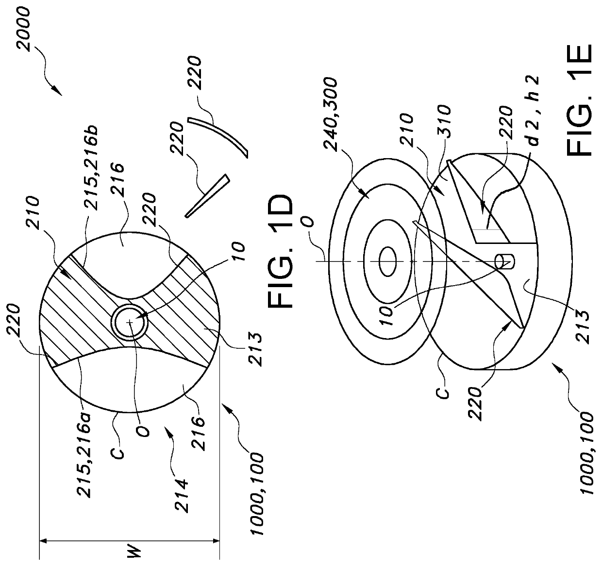
[0050]FIG. 1a schematically depicts an embodiment of the lighting system 1000 comprising a light source 10, configured to provide light source light 11, a first reflective element 210, and a lens 240,

[0051]The first reflective element 210 tapers from a first end 211 to a second end 212. Here, the firs reflective element has a conical shape. The first reflective element 210 comprises a first reflective surface 213 bridging the distance between the first end 211 and the second end 212, wherein the first reflective surface 213 is diffuse reflective, such as a diffuse white reflector. The light source 10 is at least partially circumferentially surrounded by the first reflective surface 213. Here, the light emitting surface of the light source essentially closes the second end 212 of the first reflective element.

[0052]The light source 10 is configured closer to the second end 212 than to the first end 211. As can be seen, the light source 10 is configured to direct at least part of the l...


PUM


Abstract

The invention provides a lighting system (1000) comprising a light source (10), configured to provide light source light (11), a first reflective element (210), a second reflective element (220), and a lens (240), wherein:—the first reflective element (210) tapers from a first end (211) to a second end (212), wherein the first reflective element (210) comprises a first reflective surface (213) bridging the distance between the first end (211) and the second end (212), wherein the first reflective surface (213) is diffuse reflective, and wherein the light source (10) is at least partially circumferentially surrounded by the first reflective surface (213);—the light source (10) is configured closer to the second end (212) than to the first end (211), and wherein the light source (10) is configured to direct at least part of the light source light (11) in the direction of the first end (211);—the lens (240) is configured to beam shape at least part of the light source light (11) emanating from the reflective element (210) and the light source (10); and—the second reflective element (220) is configured to redirect part of the light source light (11) to the lens (240), wherein the second reflective element is configured to specularly reflect at least part of the light source light (11) that reaches the second reflective element (220).

Description

FIELD OF THE INVENTION[0001]The invention relates to a lighting system and to a lamp comprising such lighting system. Further, the invention relates to a kit of parts for creating or adapting such lighting system. Yet further, the invention relates to a method of lighting.BACKGROUND OF THE INVENTION[0002]Wide beam street lighting is known in the art. U.S. Pat. No. 8,414,161 B2, for instance, describes an apparatus and method characterized by providing an optical transfer function between a predetermined illuminated surface pattern, such as a street light pattern, and a predetermined energy distribution pattern of a light source, such as that from an LED. A lens is formed having a shape defined by the optical transfer function. The optical transfer function is derived by generating an energy distribution pattern using the predetermined energy distribution pattern of the light source. Then the projection of the energy distribution pattern onto the illuminated surface is generated. The...

Claims


Application Information

Patent Timeline
IPC IPC(8): F21V13/04F21V7/00F21V7/04F21V3/04F21V5/04
CPCF21V7/04F21V7/041F21V13/04F21V3/049F21S8/085F21V5/045F21Y2115/10F21W2111/02F21V7/0025F21V7/046F21V11/16F21V13/10F21Y2115/30F21Y2115/15
Inventor BOONEKAMP, ERIK PAUL
Owner SIGNIFY HOLDING B V
Learn More