Signal processing method for photoelectric encoder

Active Publication Date: 2020-01-09
MITUTOYO CORP
View PDF0 Cites 2 Cited by
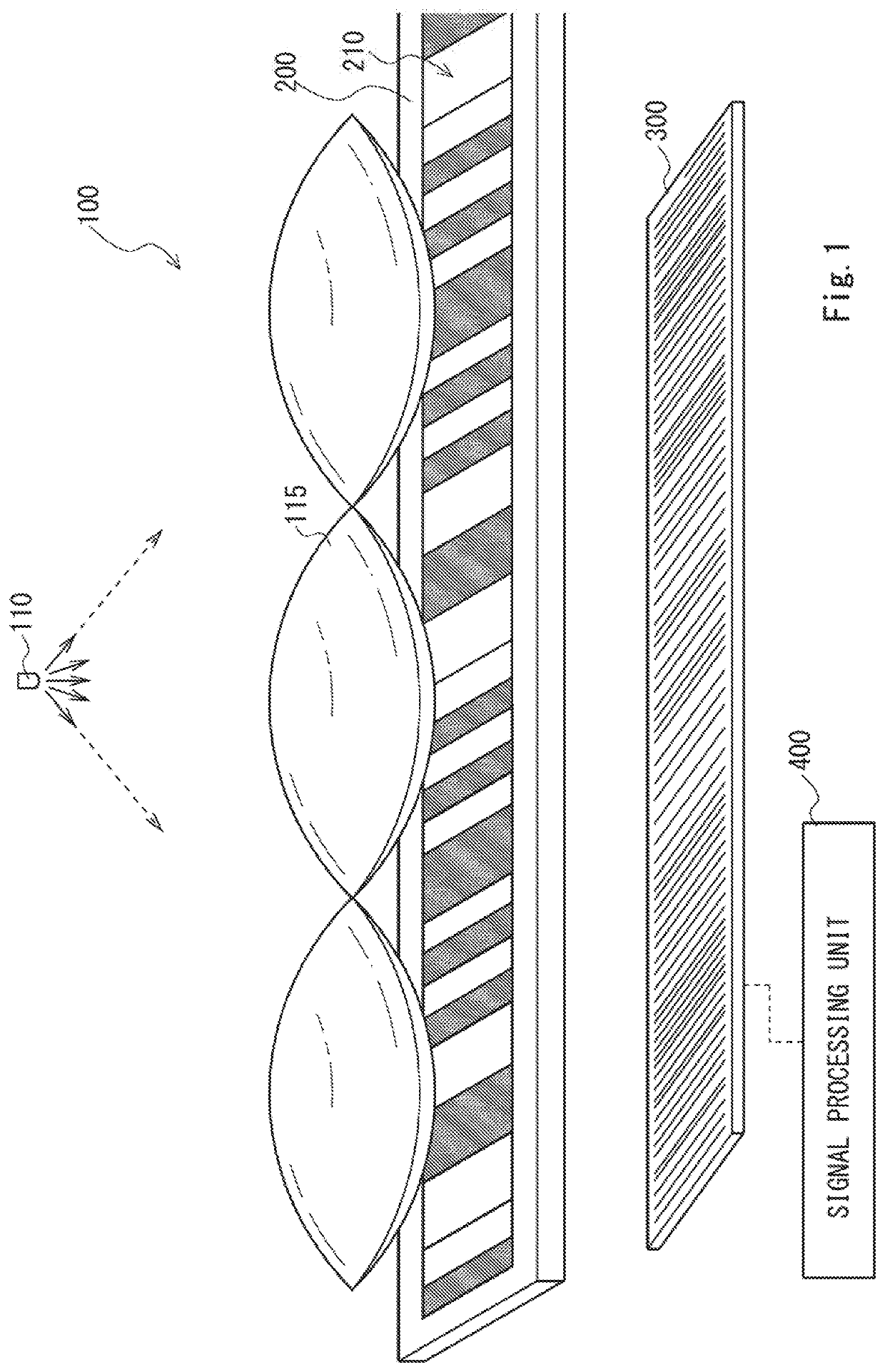
  • Summary
  • Abstract
  • Description
  • Claims
  • Application Information

AI Technical Summary

Benefits of technology

The present invention provides a method to improve the accuracy and speed of analysis for a photoelectric encoder by determining bright and dark parts in a pattern of distorted light intensity. This is achieved by setting an appropriate threshold to accurately identify the distinct parts of the pattern. This technique helps to increase the reliability and accuracy of the analysis, which is important for various applications of the photoelectric encoder.

Problems solved by technology

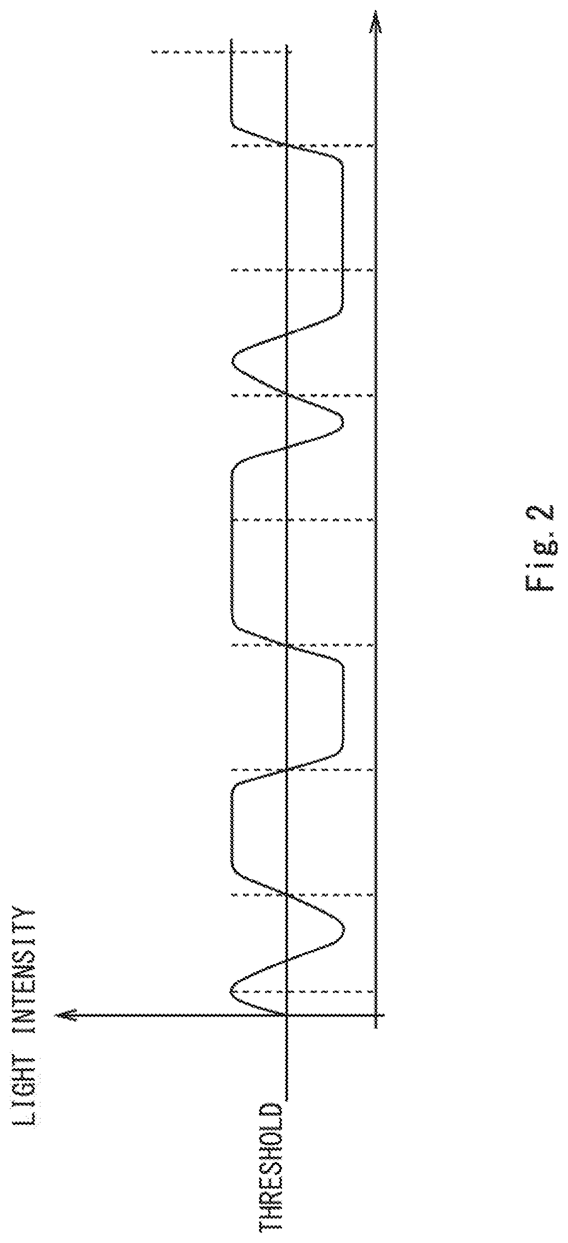
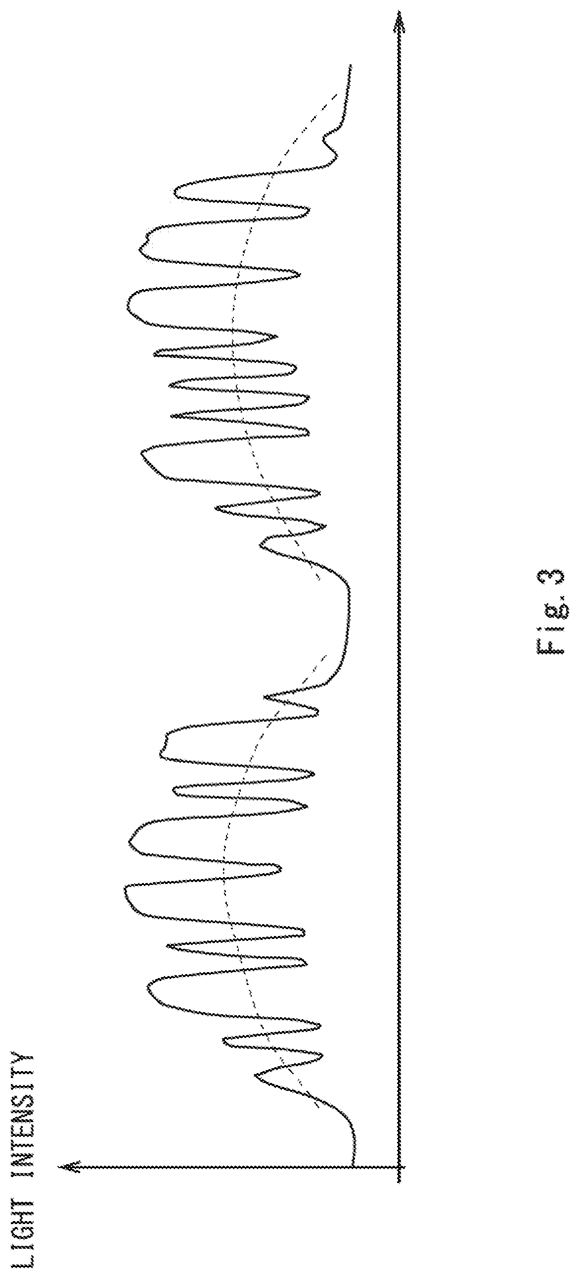
If a fixedly set threshold is applied to such a distorted bright / dark image, the bright part and the dark part cannot be correctly determined.
However, only with the simple filtering using the Fourier transform, bright / dark determination cannot be correctly performed when the light intensity distribution has large deviation.
When a lens array is used, an image cannot be obtained at a boundary part between lenses.

Method used


Image

  • Signal processing method for photoelectric encoder
  • Signal processing method for photoelectric encoder
  • Signal processing method for photoelectric encoder

Examples


first exemplary embodiment

[0072]A first exemplary embodiment of the present invention relates to a signal processing method, for a photoelectric encoder, capable of correctly determining a bright pan and a dark part in a bright / dark pattern having distorted light intensity distribution.

[0073]A feature point of the first exemplary embodiment of the present invention is to “set an appropriate threshold”. Before the feature point is described, an example of a scale pattern 210 is described.

[0074]FIG. 5 is a scale pattern of a transmission-type photoelectric absolute encoder using a pseudo random code. To correctly acquire the absolute position from this scale pattern, it is necessary to correctly and accurately detect brightness (H) and darkness (L) of bits as many as possible.

Description of Scale Pattern

[0075]The scale pattern 210 shown in FIG. 5 is an absolute (ABS) scale pattern using an M-sequence code, which is one of pseudo random code sequences. When continuous N codes in an M-sequence code pattern are t...

second exemplary embodiment

[0100]Next, a second exemplary embodiment of the present invention is described.

[0101]The second exemplary embodiment is basically similar to the first exemplary embodiment, but the light intensity of a non-image-forming region is replaced with the average intensity of the adjacent image-forming regions in the second exemplary embodiment.

[0102]FIG. 13 is a flowchart showing a procedure of a quantization process in the second exemplary embodiment.

[0103]In the second exemplary embodiment, first, a bright / dark image is classified into image-forming regions and non-image-forming regions, and the image-forming regions and the non-image-forming regions is distinguished one by one by numbering them from the left.

[0104]An example of this is shown in FIG. 14.

[0105]The image-forming regions are sequentially distinguished as a 0th image-forming region, a first image-forming region, a second image-forming region, a third image-forming region, and so on from the left. Similarly, the non-image-fo...

third exemplary embodiment

[0110]Next, a third exemplary embodiment of the present invention is described.

[0111]The third exemplary embodiment is basically similar to the second exemplary embodiment, but an image-forming region is more finely divided to replace the light intensity of each non-image-forming region with the average intensity of its adjacent image-forming regions in the third exemplary embodiment.

[0112]FIG. 18 is a flowchart showing a procedure of a quantization process in the third exemplary embodiment.

[0113]In the third exemplary embodiment, a bright / dark image is classified into image-forming regions and non-image-forming regions, and the image-forming regions and the non-image-forming regions are distinguished one by one by numbering them from the left.

[0114]At this time, each image-forming region is further divided in half to distinguish the left side as “L” and the right side as “R”.

[0115]An example of this is shown in FIG. 19.

[0116]That is, the image-forming regions are distinguished as a...


PUM


Abstract

There is provided a signal processing method, for a photoelectric encoder, capable of correctly determining a bright part and a dark part of a bright / dark pattern having distorted light intensity distribution by setting an appropriate threshold.A detector unit includes a light source, a light-receiving detector that receives transmitted light from a scale to acquire a bright / dark image, and a lens arranged between the light source and the light-receiving detector. The detector unit classifies the bright / dark image acquired by the light-receiving detector into an image-forming region corresponding to a center region of the lens and a non-image-forming region corresponding to a region except for the center region of the lens, calculates a representative value reflecting a light intensity of the image-forming region, and obtains a pre-processed bright / dark image in which the light intensity of the non-image-forming region is replaced with the representative value.

Description

INCORPORATION BY REFERENCE[0001]This application is based upon and claims the benefit of priority from Japanese patent application No. 2018-126818. filed on Jul. 3, 2018, the disclosure of which is incorporated herein in its entirety by reference.BACKGROUND OF THE INVENTION1. Field of the Invention[0002]The present invention relates to a signal processing method for a photoelectric encoder.2. Description of Related Art[0003]Photoelectric encoders are widely used as an apparatus for measuring a position or displacement, as is disclosed in JP 2017-58138A, for example.[0004]FIG. 1 shows a main configuration of a photoelectric encoder 100.[0005]The photoelectric encoder 100 includes a light source 110, a main scale 200, a light-receiving detector 300, and a signal processing unit 400. The main scale 200 has a scale pattern 210. The light-receiving detector 300 receives reflected light or transmitted light from the main scale 200. The signal processing unit 400 calculates a position or d...

Claims


Application Information

Patent Timeline
IPC IPC(8): G01D5/347
CPCG01D5/34715G01D5/347G01D5/30G01D5/34792
Inventor KATO, YOSHIAKI
Owner MITUTOYO CORP
Why Eureka
Try Eureka