Cross-laminated timber structures having reduced inner-layer material and methods of optimization

a cross-laminated timber and inner-layer material technology, applied in the field of optimization of cross-laminated timber (clt) panels, can solve the problems of difficult to define global low-carbon building materials, difficult to manufacture clt panels efficiently, and often heavy floor systems using timber beams and clt floors. achieve the effect of improving the stiffness to weight ratio of the resulting clt panel

Inactive Publication Date: 2020-01-16
MASSACHUSETTS INST OF TECH
View PDF1 Cites 3 Cited by
  • Summary
  • Abstract
  • Description
  • Claims
  • Application Information

AI Technical Summary

Benefits of technology

[0009]According to one aspect, the present invention provides a CLT panel and method of making in which one or more inner layers of the CLT panel are partially modified, in particular, by selectively removing or eliminating one or more portions of one or more inner layers. In addition, one or more layers of the overall CLT panel may be further designed to have a thickness that is different than one or more other layers of the CLT. CLT panels and methods of making are further optimized so as to provide one or more removed portions and, optionally, one or more varying layer thicknesses, therein the optimization provides an improved stiffness to weight ratio of resulting CLT panel.

Problems solved by technology

Within common construction materials, it is difficult to define global low carbon building materials since their embodied energy depends on local technologies, availability of resources, or even on the sustainability assessment itself.
However, despite their clear advantages at present, the manufacturing of CLT panels is not particularly efficient.
Further, it has been found that floor systems using timber beams and CLT floors are often heavier than steel beams with concrete composite flooring.
Further, most current projects use CLT in one-way systems, which do not take full advantage of the mechanical properties achieved through cross-layer construction.

Method used


Image

  • Cross-laminated timber structures having reduced inner-layer material and methods of optimization
  • Cross-laminated timber structures having reduced inner-layer material and methods of optimization
  • Cross-laminated timber structures having reduced inner-layer material and methods of optimization

Examples


Embodiment Construction

[0029]The following definitions are useful for interpreting terms applied to features of the embodiments disclosed herein, and are meant only to define elements within the disclosure.

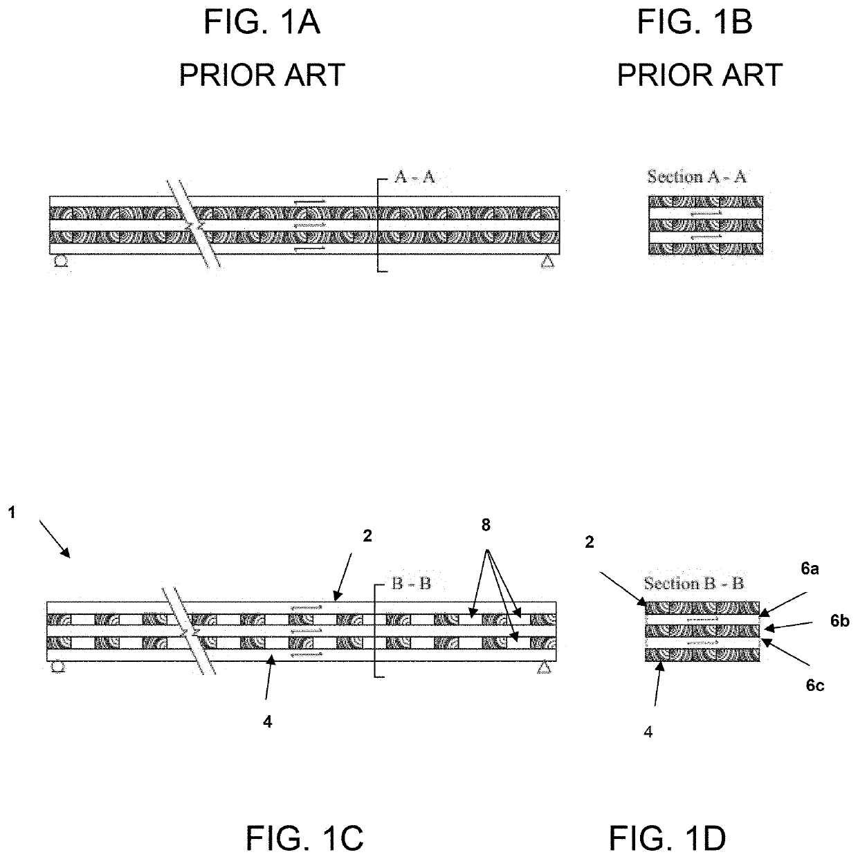
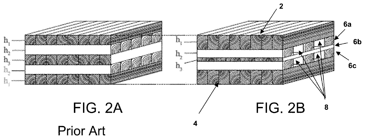
[0030]As used herein, the term “outer layers” when used to describe the outer layers of a CLT panel, refers to the outermost layers of the CLT panel. As such, the term “outer layers” refers to the bottom layer and top layer of the CLT panel.

[0031]As used herein, the term “inner layers” or “innermost layers” refers to all layers of a CLT panel disposed between the outer layers. As used herein, the terms “longitudinally extending layer” or “longitudinal layer” refers to layers of the CLT panel having a wood grain that extends lengthwise along the CLT panel, and will generally comprise the sequentially odd numbered layers beginning with a first layer (layer 1) positioned at the top of the CLT panel, the sequential layers after the first uppermost layer being numbered 2, 3, 4, etc. Longitudinal layers are a...


PUM

PropertyMeasurementUnit
stiffness-to-weight ratioaaaaaaaaaa
lengthaaaaaaaaaa
thicknessaaaaaaaaaa

Abstract

A cross-laminated timber (CLT) panel formed of multiple layers of alternating perpendicularly aligned lumber, where one or more portions of one or more inner layers are selectively removed and where one or more layers have a thickness different than one or more other layers of the CLT panel. Further, a system for optimizing the CLT panel by determining the design for the selective removal of one or more portions of one or more inner layers and, optionally, one or more varying layer thicknesses, provides a CLT panel with an improved stiffness to weight ratio and reduced material consumption.

Description

CROSS-REFERENCE TO RELATED APPLICATIONS[0001]This application claims the benefit of U.S. Provisional Patent Application Ser. No. 62 / 698,029, filed Jul. 14, 2018, entitled “Hollow and Structurally Optimized Cross-Laminated Timber Panel,” which is incorporated by reference herein in its entirety.FIELD OF THE INVENTION[0002]The present invention generally relates to improved cross-laminated timber (CLT) panels formed of multiple layers of lumber, each layer oriented perpendicular to adjacent layers, the CLT having reduced material consumption without significant change in structural behavior. More particularly, the present invention provides CLT panels and methods of optimization in which one or more portions of one or more inner layers are selectively removed and in which one or more layers have a thickness different than one or more other layers of the CLT.BACKGROUND OF THE INVENTION[0003]It is estimated that the building sector is responsible for approximately 40-50% of greenhouse g...

Claims


Application Information

Patent Timeline
Patent Type & Authority Applications(United States)
IPC IPC(8): B32B21/13B27M3/00B32B7/12
CPCB27M3/006B32B7/12B27M3/0086B32B21/13B32B2307/542B32B2307/732B32B2307/724B32B3/10B32B2607/00B32B2250/05B32B7/02B32B3/266B32B3/12B32B2307/72B32B3/20B32B2250/03
Inventor MUELLER, CAITLINMAYENCOURT, PAUL
Owner MASSACHUSETTS INST OF TECH
Why Eureka
Try Eureka